


FCQ35~14 FCQH71~140C7VEB
Split System air conditioners
4PW31577-1B
Installation manual
8
F
IELD
SETTING
Field setting must be made from the remote controller in accordance
with the installation condition.
■
Setting can be made by changing the "Mode No.", "First code
No." and "Second code No.".
■
For setting and operation, refer to "Field setting" in the
installation manual of the remote controller.
Setting ceiling height
Adjust the Second code No. according to the table below so that it
corresponds to the ceiling height of your installation. (Second code
No. is factory set to "01")
The figure of ceiling height is for air discharge in all directions.
Setting air discharge direction
For changing air discharge direction (2, 3 or 4 directions), refer to the
option handbook of the optional blocking pad kit. (Second code No. is
factory set to "01" for all-round air discharge)
Setting air filter sign
Remote controllers are equipped with liquid crystal air filter signs to
display the time to clean the air filter.
Change the Second code No. Depending on the amount of dirt or
dust in the room. (Second code No. is factory set to "01" for air filter
contamination-light)
Air filter contamination
When using wireless remote controllers it is necessary to use
address setting. Refer to the installation manual attached to the
wireless remote controller for the setting instructions.
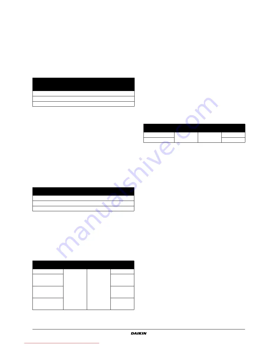
Setting indoor unit number of simultaneous operation
system
When using in simultaneous operation system mode, change the
Second code No. as shown in the table. (Second code No. is factory
set to "01" for 1 connected unit.)
When using in simultaneous operation system mode, refer to
"Simultaneous operation system individual setting" on page 8
to set
master and slave units separately.
When using wireless remote controllers
When using wireless remote controllers, wireless remote controller
address setting is necessary. Refer to the installation manual
attached to the wireless remote controller for setting instructions.
Simultaneous operation system individual setting
It is easier if the optional remote controller is used when setting the
slave unit.
Perform the following procedures when setting the master and slave
unit separately.
Procedure
(See figure 17)
1
Change the Second code No. to "02", individual setting, so that
the slave unit can be individually set. (Second code No. is
factory set to "01", unified setting.)
2
Perform field setting for the master unit.
3
Turn off the main power supply switch after (2).
4
Detach remote controller from the master unit and connect it to
the slave unit.
5
Turn on the main power supply switch again, and as in (1),
change the Second code No. to "02", individual setting.
6
Perform field setting for the slave unit.
7
Turn off the main power supply switch after (6).
In case there are 2 or more slave units, repeat steps (4) to (7) for
all slave units.
8
Detach the remote controller from the slave unit after the setting,
and reattach to the master unit. This is the end of the setting
procedure.
You do not need to rewire the remote controller from the master unit if
the optional remote controller for slave unit is used. (However,
remove the wires attached to the remote controller terminal board of
the master unit.)
T
EST
OPERATION
Refer to
"For the following items, take special care during
construction and check after installation is finished" on page 2
.
After finishing the construction of refrigerant piping, drain piping, and
electric wiring, conduct test operation accordingly to protect the unit.
Test operation after installing decoration panel
1
Open the gas side stop valve.
2
Open the liquid side stop valve.
3
Electrify crank case heater for 6 hours.
4
Set to cooling operation with the remote controller and start
operation by pushing ON/OFF button.
Ceiling height (m)
Mode
No.
First
code No.
Second
code No.
FCQ35~140
FCQH71
FCQH100~140
≤
2.7
≤
3.2
N
13 (23)
0
01
>2.7 or
≤
3.0
>3.2 or
≤
3.6
H
13 (23)
0
02
>3.0 or
≤
3.5
>3.6 or
≤
4.2
S
13 (23)
0
03
Setting
Display
interval
Mode No.
First code
No.
Second
code No.
Light
±2500 hrs
10 (20)
0
01
Heavy
±1250 hrs
10 (20)
0
02
No display
—
10 (20)
3
02
Setting
Mode No.
First code No.
Second
code No.
Pair system (1 unit)
11 (21)
0
01
Simultaneous
operation system
(2 unit)
02
Simultaneous
operation system
(3 unit)
03
Simultaneous
operation system
(4 unit)
04
1
Main power supply
2
Main switch
3
Fuse
4
Remote controller (optional accessories)
5
Indoor unit (Master)
6
Indoor unit (Slave)
Setting
Mode No.
First code No.
Second code
No.
Unified setting
11 (21)
1
01
Individual setting
02
Downloaded from AC-Manual.com Manuals


