background image

9

English

Make sure wiring the units, ground wiring and remote controller wiring are not caught inside the indoor 
unit.

When screwing in the indoor unit

Remove the front grill. 

(Refer to Fig. 7)

Secure the indoor unit to the installation panel (1) with the securing 
screws (6). 

(Refer to Fig. 11)

5. REFRIGERANT PIPING WORK

〈〈〈〈

For refrigerant piping of outdoor units, see the installation manual attached to the outdoor unit.

〉 〉 〉 〉 

〈〈〈〈

Execute heat insulation work completely on both sides of the gas piping and the liquid piping. 

Otherwise, a water leakage can result sometimes.

〉 〉 〉 〉 

(When using a heat pump, the temperature of the gas piping can reach up to approximately 120°C, so use 
insulation which is sufficiently resistant.)

〈〈〈〈

Also, in cases where the temperature and humidity of the refrigerant piping sections might exceed 

30°C or RH80 %, reinforce the refrigerant insulation. (20 mm or thicker) Condensation may form on the 
surface of the insulating material.

〉〉〉〉

〈〈〈〈

Before refrigerant piping work, check which type of refrigerant is used. Proper operation is not pos-

sible if the types of refrigerant are not the same.

〉〉〉〉

CAUTION

• Use a pipe cutter and flare suitable for the type of refrigerant.
• Apply ester oil or ether oil around the flare section before connecting.
• To prevent dust, moisuture or other foreign matter from infiltrating the tube, either pinch the end 

or cover it with tape.

• Do not allow anything other than the designated refrigerant to get mixed into the refrigerant 

circuit, such as air, etc. If any refrigerant gas leaks while working on the unit, ventilate the room 
thoroughly right away.

The outdoor unit is charged with refrigerant.

Use copper alloy seamless pipes (ISO 1337)

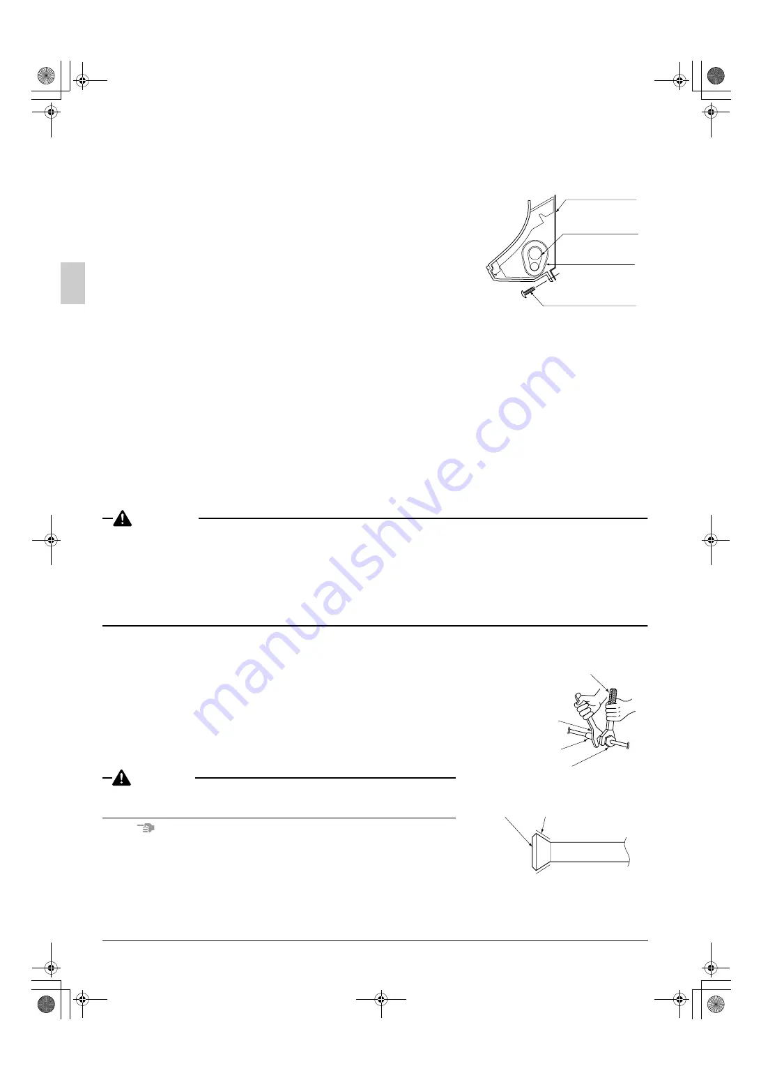
Be sure to use both a spanner and torque wrench together, as shown 
in the drawing, when connecting or disconnecting pipes to/from the 
unit.

 (Refer to Fig. 12)

Refer to “Table 2” for the dimensions of flare nut spaces.

When connecting the flare  nut, coat the flare section (both inside and 
outside) with ester oil or ether oil, rotate three or four times first, then 
screw in.

 (Refer to Fig. 13)

CAUTION

Over-tightening may cause the flare nuts to crack or the refrigerant to 
leak. 

NOTE

Use the flare nut included with the unit main body.

Installation panel 
(accessory) (1)

Refrigerant piping

Insulating tape 
(accessory) (4)

M4 × 12L 
(accessory) (6)

Fig. 11

Torque wrench

Spanner

Piping union

Flare nut

Fig. 12

Ester oil or ether oil

Fig. 13

01_EN_3P083811-3T.fm  Page 9  Friday, September 3, 2004  10:17 AM

Summary of Contents for FAY71LVE

Page 1: ...RUCTIONS AVANT L INSTALLATION CONSERVER CE MANUEL A PORTEE DE MAIN POUR REFERENCE ULTERIEURE LEA CUIDADOSAMENTE ESTAS INSTRUCCIONES ANTES DE INSTALAR GUARDE ESTE MANUAL EN UN LUGAR A MANO PARA LEER EN...

Page 2: ...ller andra normgivande dokument under f ruts ttning att anv ndning sker i verensst mmelse med v ra instruktioner respektive utstyr er i overensstemmelse med f lgende standard er eller andre normgivend...

Page 3: ...s documento s normativo s desde que estes sejam utilizados de acordo com as nossas instru es overholder f lgende standard er eller andet andre retningsgivende dokument er forudsat at disse anvendes i...

Page 4: ...ion work Do not try to install the machine yourself Improper installation may result in water leakage electric shocks or fire Perform installation work in accordance with this installation manual Impr...

Page 5: ...ater leakage b where corrosive gas such as sulfurous acid gas is produced Corroding copper pipes or soldered parts may result in refrigerant leakage c near machinery emitting electromagnetic waves Ele...

Page 6: ...he Installation manual included with the remote controllers Table 1 NOTE If the customer wishes to use a remote controller that is not listed above select a suitable remote controller after consulting...

Page 7: ...likely to occur Check Are the indoor and outdoor unit fixed firmly The units may drop vibrate or make noise Is the gas leak test finished It may result in insufficient cooling Is the unit fully insul...

Page 8: ...the paper pattern for installation 3 so refer to it when con sidering the necessity for reinforcing the location 3 The indoor unit may not be directly installed on the wall Use the attached installati...

Page 9: ...r a total of 2 bolts on either side If dealing with concrete use commercially available foundation bolts M8 M10 3 If using the left bottom left right or bottom right positions for the piping cut out t...

Page 10: ...ot to catch the horizontal flaps remove the front grill by pulling in the direction of the arrow Remove the drain plug the insulation tubing and the drain hose from the drain pan and replace Refer to...

Page 11: ...e wiring the units ground wirings Then fix them securely on the refrigerant pipe Seal the piping through hole with putty corking material 9 Push on both bottom edges of the indoor unit using both hand...

Page 12: ...lare suitable for the type of refrigerant Apply ester oil or ether oil around the flare section before connecting To prevent dust moisuture or other foreign matter from infiltrating the tube either pi...

Page 13: ...out nitrogen substitution NOTE 1 or while inserting nitrogen into the refrigerant piping NOTE 2 Once this is done connect the indoor unit with a flared or a flanged connection NOTES 1 Refer to the Man...

Page 14: ...section of the drain hose which is indoors Refer to Fig 17 Make sure the diameter of the piping is the same as the piping hard vinyl chloride nominal diameter 13mm or bigger Insulating tubing tape In...

Page 15: ...r also to WIRING DIAGRAM attached to the unit body For remote controller wiring details refer to the installation manual attached to the remote controller All wiring must be performed by an authorized...

Page 16: ...in case of no protection 2 For European and Asian market Vinyl cord with sheath or cable Insulated thickness 1 mm or more For Australian regular Shield wire Insulated thickness 1 mm or more Wire Size...

Page 17: ...en firmly secure using the included clamp small 5 according to the figure Refer to Fig 20 1 2 3 REMOTE CNTRL TRANSMISSION WIRING F1 F2 P1 P2 Fig 20 In case of using the power supply terminal together...

Page 18: ...round crimp style terminals for connecting wires to the power supply terminal block Refer to Fig 21 If unavailable observe the following points when wiring Do not connect wires of different gauge to t...

Page 19: ...ntroller that suits the indoor unit which has the most functions as attached swing flap 4 For simultaneous operation system connect the remote controller cord to the master unit 1 2 3 P1 P2 1 2 3 P1 P...

Page 20: ...ress setting is necessary Refer to the installation manual attached to the wireless remote controller for setting instructions 9 3 SETTING INDOOR UNIT NUMBER OF SIMULTANEOUS OPERATION SYSTEM When usin...

Page 21: ...to 9 1 to 9 2 for the slave unit 7 Turn off the main power supply switch after 6 8 If there is more than one slave unit repeat steps 4 to 7 9 Detach the remote controller from the slave unit after th...

Page 22: ...l block for remote controller 2 Actuation The following table explains FORCED OFF and ON OFF OPERATIONS in response to Input A 3 How to select FORCED OFF and ON OFF OPERATION Turn the power on and the...

Page 23: ...l display remote controller 1 With the wired remote controller NOTE 1 When the operation stops due to trouble operation lamp flashed and and the error code are indicated on the liquid crystal display...

Page 24: ...ype of indoor or outdoor unit the malfunction code may or may not be displayed Microcomputer normal monitor Transmission normal monitor Details HAP H1P HBP H2P FAY L FAYP L FAQ BUV1B Indoor unit is no...

Page 25: ...ntion outdoor unit Compressor possibly locked LC Transmission malfunction between the outdoor control units inverters outdoor unit P1 Open phase outdoor unit P3 PC board temperature sensor malfunction...

Page 26: ...NIT 2 NOTE 4 3 WIRED REMOTE CONTROLLER 4 CONTROL BOX INDOOR 5 RECEIVER DISPLAY UNIT ATTACHED TO WIRELESS REMOTE CONTROLLER 6 IN CASE OF SIMULTANEOUS OPERATION SYSTEM 7 INDOOR UNIT MASTER 8 INDOOR UNIT...

Page 27: ...T EMITTING DIODE DEFROST ORANGE SELECTOR SWITCH MAIN SUB SELECTOR SWITCH WIRELESS ADDRES SET X15A X35A CONNECTOR FLOAT SWITCH CONNECTOR GROUP CONTROL ADAPTOR SS1 R1T SELECTOR SWITCH MAIN SUB THERMISTO...

Page 28: ...IODE DEFROST ORANGE SELECTOR SWITCH MAIN SUB SELECTOR SWITCH WIRELESS ADDRES SET X15A X35A CONNECTOR FLOAT SWITCH CONNECTOR GROUP CONTROL ADAPTOR SS1 R1T SELECTOR SWITCH MAIN SUB THERMISTOR AIR WIRING...

Page 29: ...AIN SUB SELECTOR SWITCH WIRELESS ADDRES SET X15A X35A CONNECTOR FLOAT SWITCH CONNECTOR GROUP CONTROL ADAPTOR R1T SS1 THERMISTOR AIR SELECTOR SWITCH MAIN SUB WIRING DIAGRAM 2 IN CASE USING CENTRAL REMO...

Page 30: ...0412 HT 3P083811 3U EM02A063D 00_CV_3P083811 3U fm Page 2 Tuesday November 30 2004 4 30 PM...

Reviews: