


6 Preparation
Installation manual
11
EZESHP20 EZLSHP20AUAW1B
Exigo E1500 Trailer Refrigeration Unit
4P726857-1 – 2023.03
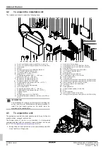
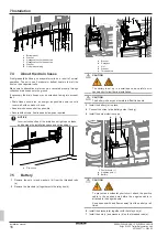
a
Unit (2076×2226 mm)
b
Roof of the cold room
c
Cold room holes (Ø14 mm) for mounting the M12 bolts
d
Cutout (1704×1181 mm)
2
Install the 8 Exigo frame bolts (c) through the 8 holes you have
made in the cold room.
3
Fix the bolts (c) in place with the self-tapping screws (h).
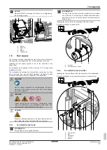
f
a
e
g
d
b
h
c
h
c
a
Unit
b
Roof of the cold room
c
Exigo frame bolt
d
Cold room
e
Protrusion of the unit
f
Insulation
g
Vertical and horizontal framing (not provided in
installation kit)
h
Self-tapping screw (5.5×22, DIN 7981 INOX A2)
4
Make 4 holes (a) in the front of the cold room.
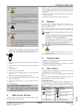
300
250
18
225
a
a
a
a
a
Holes for mounting the heat shield
Mounting the heat shield is left to the expertise of the bodybuilder;
self tapping screws (d) or a large head rivets (c) are both possibilities
included in the installation kit that is supplied with the unit, see
"4.2 To unpack the installation kit"
8]. The size of the holes must fit
the chosen option.
A typical installation is shown below.
5
Install the heat shield (b) on the cold room using the self
tapping screws (d) or using large head rivets (c).
c
b
a
d
a
Hole for mounting the heat shield
b
Heat shield
c
Rivet (4.8×16, large head)
d
Self tapping screw (5.5×22, DIN 7981 FE/ZN)
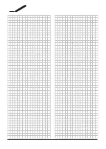
The cutout (a) will accommodate the evaporator protrusion (c) of the
unit.
The bolts (b) will engage in the mounting holes (d) of the unit's
frame.
The heat shield (e) will protect the cold room from the heat of the
muffler.
a
c
b
d
e
a
Cutout
b
Bolts
c
Protrusion of the unit
d
Holes in the unit's frame
e
Heat shield
6.2
To prepare the unit
INFORMATION
The pallet is larger than the unit base and must be
removed before bringing the unit in installation position.


