DEIMHP0140521_00EN
26
EWYT~CZ / EWAT~CZ
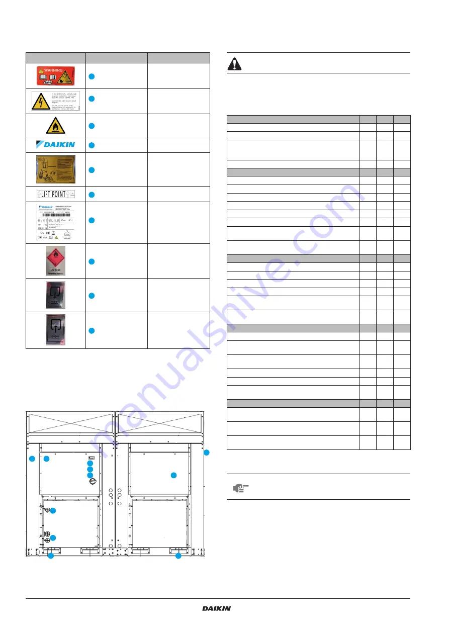
8. List of tHe LabeLs aPPLieD to tHe
unit
Labels
Description
Location
Generical warning
On the electric panel
(outside)
Hazardous voltage
warning
On the electric panel
(outside)
A2L symbol
On the electric panel
(outside)
Manufacturer’s logo
On the electric panel
(outside)
Lifting instruction*
One on the unit frame
and one on the
packaging
Lift point label
One on the unit panel
near the unit lifting holes
Unit ID plate
information
On the unit frame
(outside)
UN 3358 labels*
On the packaging
Water outlet
On the unit panel near
the outlet connection
Water inlet
On the unit panel near
the inlet connection
* Labels on the unit packaging
Table 12 –
Labels applied to the Unit
With the exception of the unit’s identification plate, which is always in
the same position, the other plates may be located in different
positions depending on the model and the options present on the unit.
Figure 21 –
Labels on the unit
9. CHeCKs for tHe first startuP
The unit must be started for the first time ONLY by
authorized DAIKIN personnel.
The unit must absolutely not be put into operation, even if for a very
short period, without having first meticulously checking the following
list in its entirety.
General
Yes
No
N/A
Check for external damage
Open all isolation and / or shutoff valves
Verify that the unit is pressurized with refrigerant in all
of its parts before making the connection to the
hydraulic circuit.
Check the oil level in the compressors
Chilled Water
Yes
No
N/A
Piping complete
Water System filled and vented
Pumps installed & operational (rotation checked)
Strainers installed and clean
Controls (3way valves, bypass valves, etc.) operable
Flow switch installed.
Water system operated and flow balanced to meet
unit design requirements
Proper glycol percentage for the application in
accordance with Daikin specifications
Condenser Water
Yes
No
N/A
Cooling tower flushed, filled and piping vented
Pumps installed & operational (rotation checked)
Strainers installed and clean
Controls (3way valves, bypass valves, etc.) operable
Water system operated and flow balanced to meet
unit design requirements
Proper glycol percentage for the application in
accordance with Daikin specifications
Electrical
Yes
No
N/A
Power leads connected to unit main terminal block
Power leads have been checked for proper electrical
phasing UVW for L1, L2, & L3 respectively.
All interlock wiring complete and complies with Daikin
specifications
Pump starter and interlocks wired
Cooling tower fans and controls wired
Wiring complies with National Electrical Code and
local codes
Miscellaneous
Yes
No
N/A
Unit installed in accordance with Daikin IOM
specifications (leveling, space requirements, …)
Thermometer wells, thermometers, gauges, control
wells, controls, etc., installed
A minimum system load of 60% of machine capacity
is available for testing and adjusting controls
Table 13 –
Checks before starting up the unit
NOTE
This list must be completed and sent to the local Daikin
Service department at least two weeks before the
startup date.
Summary of Contents for EWAT016CZN-A1
Page 2: ......
Page 28: ...Notes...


