


D-EIMAC00907-16EN - 13/20
Electrical Installation
General specifications
All electrical connections to the unit must be carried out
in compliance with laws and regulations in force.
All installation, management and maintenance activities
must be carried out by qualified personnel.
Refer to the specific wiring diagram for the unit you have
bougth. Should the wiring diagram not be on the unit or
should it have been lost, please contact your
manufacturer representative, who will send you a copy.
In case of discrepance between wiring diagram and
electrical panel/cables, please contact the manufacturer
representative.
Only use copper conductors. Failure to use copper conductors
could result in overheating or corrosion at connection points
and could damage the unit.
To avoid interference, all control wires must be connected
separately from the power cables. Use different electrical
passage ducts for this purpose.
Particular care must be taken when realizing wire connections
to the switchbox; if not properly sealed, cable entries may
allow ingress of water into the switchbox which may cause
damage to the equipment inside.
Before any installation and connection works, the unit
must be switched off and secured. Since this unit
includes inverters, the intermediate circuit of the
capacitors remains charged with high voltage for a short
period of time after being switched off. Do not operate to
the unit before 5 minutes after the unit has been
switched off.
This unit includes non-linear loads such as inverters, which
have a natural current leakage to earth. If an Earth Leakage
Detector is installed upstream the unit, a type B device with a
minimum threshold of 300 mA must be used.
This product complies with EMC standards for industrial
environments. Therefore it is not intended for use in residential
areas, e.g. installations where the product is connected to a
low voltage public distribution system. Should this product
need to be connected to a low voltage public distribution
system, specific additional measures will have to be taken to
avoid interference with other sensitive equipment.
Operation
Operator’s responsibilities
It is essential that the operator is appropriately trained and
becomes familiar with the system before operating the unit. In
addition to reading this manual, the operator must study the
microprocessor operating manual and the wiring diagram in
order to understand start-up sequence, operation, shutdown
sequence and operation of all the safety devices.
During the unit
’s initial start-up phase, a technician authorized
by the manufacturer is available to answer any questions and
to give instructions as to the correct operating procedures.
The operator must keep a record of operating data for every
installed unit. Another record should also be kept of all the
periodical maintenance and servicing activities.
If the operator notes abnormal or unusual operating conditions,
he is advised to consult the technical service authorized by the
manufacturer.
Maintenance
Routine maintenance
This chiller must be maintained by qualified technicians.
Before beginning any work on the system the personnel
shall assure that all security precautions have been taken.
Neglecting unit maintenance in these environments, could
degrade all parts of the units (coils, compressors, frames,
pipes, etc..) with negative effect on performances and
functionality.
There are two different levels of maintenance, which can be
chosen according to the type of application (critical/non critical)
or to the installation environment (highly aggressive).
Examples of critical applications are process cooling, data
centres, etc.
Highly Aggressive Environments can be defined as the follows:
Industrial environment (with possible concentration
of fumes result of combustion and chemical process)
Costal environment;
Highly polluted urban environment;
Rural environment close to of animal excrement and
fertilizers, and high concentration of exhaust gas
from diesel generators.
Desert areas with risk of sandstorms;
Combinations of the above
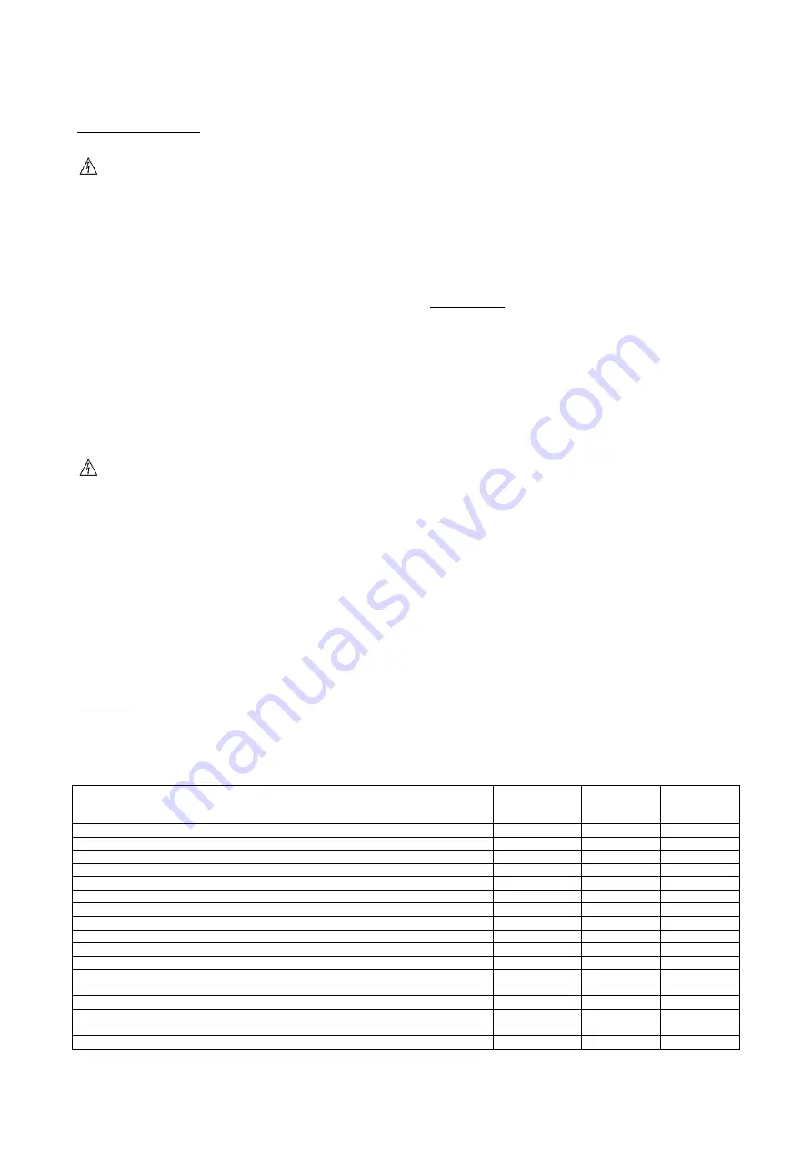
Table 2 lists all Maintenance activities for standard applications
and standard environment.
Table 3 lists all Maintenance activities for critical applications
or highly aggressive environment.
Following below instructions is mandatory for cases listed
above, but also advised for units installed in standard
environments.
Table 2
– Standard Routine Maintenance Plan
List of Activities
Weekly
Monthly
(Note 1)
Yearly/Seas
Onal
(Note 2)
General:
Reading of operating data (Note 3)
X
Visual inspection of unit for any damage and/or loosening
X
Verification of thermal insulation integrity
X
Clean and paint where necessary
X
Analysis of water (6)
X
Check of flow switch operation
X
Electrical:
Verification of control sequence
X
Verify contactor wear
– Replace if necessary
X
Verify that all electrical terminals are tight
– Tighten if necessary
X
Clean inside the electrical control board
X
Visual inspection of components for any signs of overheating
X
Verify operation of compressor and oil heater
X
Measure compressor motor insulation using the Megger
X
Clean air intake filters of the electrical panel
X
Summary of Contents for EWAD TZ
Page 17: ...D EIMAC00907 16EN 17 20...
Page 18: ...D EIMAC00907 16EN 18 20...
Page 19: ...D EIMAC00907 16EN 19 20...


