


19
ating temperature. A manometer should be connected to the
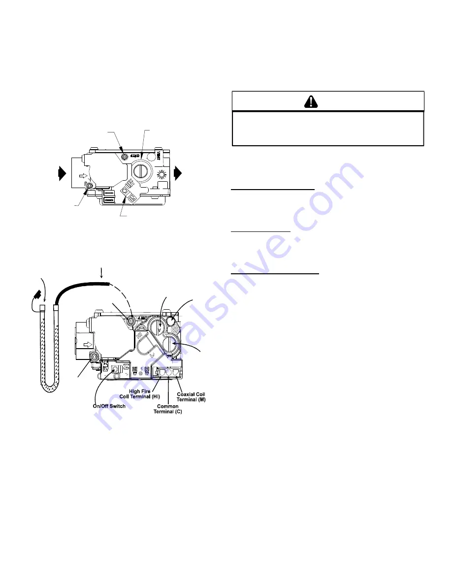
gas valve to verify pressure is within the specified range (see
following figures for manometer connections). Clockwise
rotation of the pressure regulator screw increases pressure
and gas flow rate. Turn screw counterclockwise to decrease
pressure and gas flow rate. After adjustment the furnace
temperature rise must be within the range specified on the
unit data plate.
NOTE:
Thermal efficiency of the furnace is a
product efficiency rating determined under continuous oper
-
ating conditions independent of any installed system.
Pressure Regulator
Adjustment
(Under Cap Screw)
Gas Valve
On/Off
Selector
Switch
INLET
OUTLET
Inlet Pressure
Tap
Outlet Pressure
Tap
White-Rodgers 36G22 - Single Stage
Inlet
Pressure Boss
Low Fire
Regulator Adjust
Manometer
Manometer
Hose
High Fire Regulator
Adjust
Regulator
Vent
Outlet
Pressure Boss
Open to
Atmosphere
White-Rodgers 36G54 (2-Stage) Connected to Manometer
Pressure Adjustments
To connect manometer to gas valve:
1. Back outlet pressure test screw (inlet/outlet pressure
boss) out one turn (counterclockwise, not more than one
turn).
2. Attach a hose and manometer to the outlet pressure boss
of the valve.
To remove manometer from gas valve:
1. Remove manometer hose from outlet pressure boss.
2. Turn outlet pressure test screw in to seal pressure port
(clockwise, 7 in-lb. minimum).
3. Turn on electrical power and gas supply to the system.
4. Turn on system power and energize valve.
5. Using a leak detection solution or soap suds, check for
leaks at pressure boss screw. Bubbles forming indicate a
leak. SHUT OFF GAS AND FIX ALL LEAKS IMMEDIATE-
LY.
T
O
PREVENT
UNRELIABLE
OPERATION
OR
EQUIPMENT
DAMAGE
,
THE
GAS
MANIFOLD
PRESSURE
MUST
BE
AS
SPECIFIED
ON
THE
UNIT
RATING
PLATE
. O
NLY
MINOR
ADJUSTMENTS
SHOULD
BE
MADE
BY
ADJUSTING
THE
GAS
VALVE
PRESSURE
REGULATOR
.
CAUTION
6. Relight all other appliances turned off in step 1. Be sure all
pilot burners are operating.
Main Burner Flame Check
Flames should be stable, soft and blue (dust may cause or-
ange tips but they must not be yellow) and extending directly
outward from the burner without curling, floating or lifting off.
NOx Screen Check
Verify that the alignment of the NOx screens is at 6 o’ clock.
In jurisdictions that do not require low NOx emissions, NOx
screens may be removed.
Temperature Rise Check
Check the temperature rise through the unit by placing ther-
mometers in supply and return air registers as close to the
unit as possible. Thermometers must not be able to sample
temperature directly from the unit heat exchangers, or false
readings could be obtained.
1. All registers must be open; all duct dampers must be in their
final (fully or partially open) position and the unit operated
for 15 minutes before taking readings.
2. The temperature rise must be within the range specified on
the rating plate.
NOTE:
Air temperature rise is the temperature difference
between supply and return air.
With a properly designed system, the proper amount of tem-
perature rise will normally be obtained when the unit is op-
erated at rated input with the recommended blower speed.
If the correct amount of temperature rise is not obtained, it
may be necessary to change the blower speed. A higher
blower speed will lower the temperature rise. A slower blow-
er speed will increase the temperature rise.
NOTE:
Blower speed MUST be set to give the correct air
temperature rise through the unit as marked on the rating
plate.
NORMAL SEQUENCE OF OPERATION
h
eating
This unit has one (RS) Manual Reset Limit Control Switch.
Check the limit to make sure it has not tripped. The limit may
arrive at the job site tripped as a result of shipping shock.


