


17
NOTE:
Except during brief periods when gas pressures are
being measured by qualified service personnel, the furnace
access panel must always be secured in place when the fur-
nace is in operation. An inspection port in the access panel
is provided to monitor the flame.
The first step in checking out the gas-fired furnace is to test
the gas supply piping to the unit for tightness and purge the
system of air using methods outlined in the latest edition of
the National Fuel Gas Code ANSI Z223.1. Verify that the
disconnect switch is in the “OFF” position. A soapy water
solution should be used to check for gas leaks. Since the
unit is subject to considerable jarring during shipment, it is
extremely important that all gas connections and joints be
tested for tightness. Gas piping downstream from the unit
inlet should be checked for leaks during the subsequent se-
quence check.
The supply gas pressure should be adjusted to 7.0” w.c. on
natural gas and 11.0” on LP gas with the gas burners oper-
ating. If there is more than one unit on a common gas line,
the pressures should be checked with all units under full fire.
A supply pressure tap is provided on the upstream side of
the gas valve. A manifold pressure tap is provided on the
gas valve. The normal manifold pressure for full input is 3.5”
w.c. on natural gas and 9.5” w.c. for propane gas. Low fire
natural gas 2.0” w.c., 6.0” low fire propane gas. Minimum
gas supply pressure is 5.5” w.c. for natural gas and 11.0” for
propane gas. In order to obtain rating, gas supply pressure
must be 11.0” w.c. for propane gas.
The pressure regulator on LP gas models is adjusted for 9.5”
w.c. manifold pressure and is intended to prevent over-fir
-
ing only. Do not attempt adjustment of the built-in pressure
regulator unless the supply pressure is at least 7.0” w.c. on
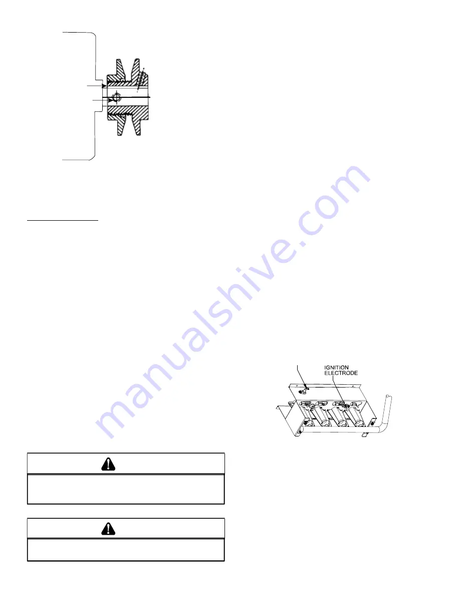
natural gas or 13.0” w.c. on propane gas. Check the location
of the ignition electrode and the flame sensor for correct
gap setting.
FLAME
SENSOR
Flame Sensor and Ignition Electrode Location
C
B
VL & VM
NOTE:
Do NOT operate sheave with flange projecting be
-
yond the hub end.
GAS SYSTEM CHECK
Pre-Operation Checks
1. Close the manual gas valve external to the unit.
2. Turn off the electrical power supply to the unit.
3. Set the room thermostat to its lowest possible setting.
4. Remove the heat exchanger door on the side of the unit
by removing screws.
5. This unit is equipped with an ignition device which auto-
matically lights the main burner. DO NOT try to light burn-
er by any other method.
6. Move the gas control valve switch to the OFF position. Do
not force.
7. Wait five minutes to clear out any gas.
8. Smell for gas, including near the ground. This is important
because some types of gas are heavier than air. If you
have waited five minutes and you do smell gas, imme
-
diately follow the warnings on page 3 of this manual. If
having waited for five minutes and no gas smell is noted,
move the gas control valve switch to the ON position.
9. Replace the heat exchanger door on the side of the unit.
10. Open the manual gas valve external to the unit.
11. Turn on the electrical power supply to the unit.
12. Set the thermostat to desired setting.
g
as
s
uPPly
P
ressures
& r
egulatOr
a
djustments
S
HOULD
OVERHEATING
OCCUR
OR
THE
GAS
SUPPLY
FAIL
TO
SHUT
OFF
,
TURN
OFF
THE
MANUAL
GAS
SHUTOFF
VALVE
EXTERNAL
TO
THE
UNIT
BEFORE
TURNING
OFF
THE
ELECTRICAL
SUPPLY
.
WARNING
T
O
AVOID
PROPERTY
DAMAGE
,
PERSONAL
INJURY
OR
DEATH
,
DO
NOT
FIRE
GAS
UNIT
WITH
FLUE
BOX
COVER
REMOVED
.
WARNING


