


System Settings
Menu Item
92
94
See pages
to
• Limitations of the simple interlock function
In the simple interlock function, setting the inconsistent input/output conditions is
allowed as described below.
* Priority of the interlock programs is determined in such a way that the lower program
has a higher priority and the output 2 has a higher priority than the output 1.
Example 1)
When the interlock input point and the control target are same
Result : 1-00 cannot be initiated. (Even if it has been initiated, it should be stopped by
the interlock control function.)
Example 2)
When the interlock input point and the control target are same but the
control items specify opposite operations
Result : The interlock output 2 with a higher priority is executed. (1-01 stops.)
The settings of the input/output conditions as described in the
example 3 below
will cause a failure of the air conditioning unit;
therefore never use these settings
.
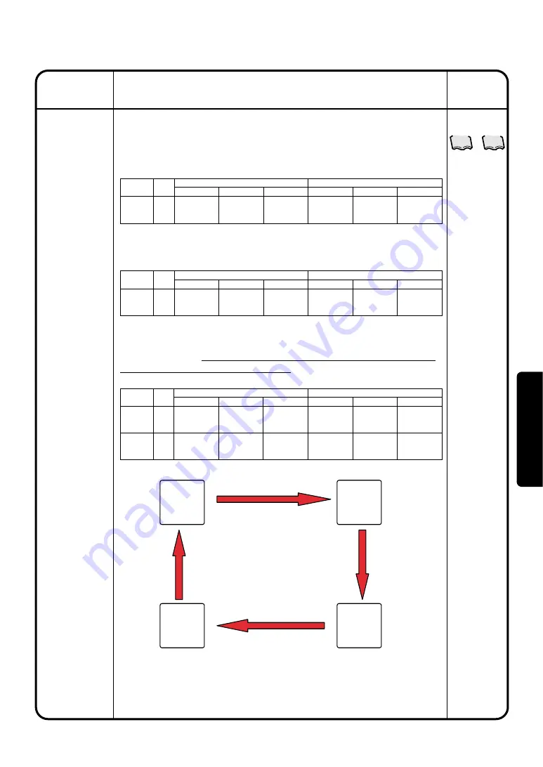
Example 3)
When the interlock input point and the control output fall into a loop
Operation
(Reference)
Description
60
Simple
Interlock
Interlock
Program
Number
Program 1
Interlock
input point
1-00
Input Condition
Any one or more
of the groups ON
Control Item
Stop
Interlock Output 1
Control Target
1-00
Input Condition
No detection
Control Item
–
Interlock Output 2
Control Target
–
Interlock
Program
Number
Program 1
Interlock
input point
1-00
Input Condition
Any one or more
of the groups ON
Control Item
Start operation
Interlock Output 1
Control Target
1-01
Input Condition
Any one or more
of the groups OFF
Control Item
Stop
Interlock Output 2
Control Target
1-01
Interlock
Program
Number
Program 1
Program 2
Interlock
input point
1-00
1-01
Input Condition
Any one or more
of the groups ON
Any one or more
of the groups ON
Control Item
Start operation
Stop
Interlock Output 1
Control Target
1-01
1-00
Input Condition
Any one or more
of the groups OFF
Any one or more
of the groups OFF
Control Item
Stop
Start operation
Interlock Output 2
Control Target
1-01
1-00
1-00
Start
1-01
Start
1-00
Stop
1-01
Stop
Program 2
Interlock
output 2
<1-01 operation control>
Program 1
Interlock output 1
Program 2
Interlock
output 1
<1-00
operation
control>
<1-00
stop
control>
<1-01 stop control>
Program 1
Interlock output 2
Result : The interlock program is repeated endlessly. In the example
above, the air conditioning units : 1-00 and 1-01 repeat
start/stop operations endlessly.
Oper
ation


