background image

10

English

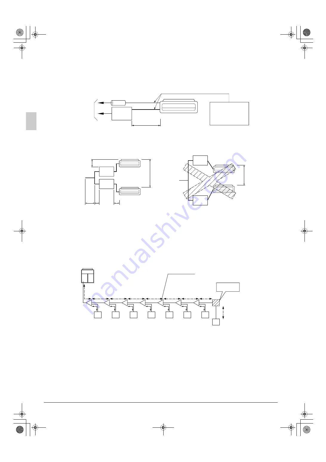
Piping connection procedure

Make sure the length of the refrigerant piping between the BEV unit and the indoor unit is no more than 5m 
and that the difference in height is at least 4m.

(1) Connection example for the indoor unit

Only one indoor unit may be connected to each BEV unit.

(2) Height difference between indoor units

Install the BEV unit in the 15m range of difference in height between the indoor units.

Make sure the difference in height between the BEV unit and the indoor unit is no more than 4m.

(3) Allowable length after split (actual piping length)

B+C

35m (length from the first branch piping to the indoor unit)

(4) Additional refrigerant amount

When measuring the amount of additional to refrigerant to fill, include the length of the liquid piping 
between the BEV unit and the indoor unit.

Additional filling amount = a+b+c+d+e+f+g+h+i+j+k+l+m+n+p+q

Refer also to the installation manual included with the outdoor unit.

7. ELECTRIC WIRING WORK 

7-1 GENERAL INSTRUCTIONS 

All field supplied parts and materials and electric works must conform to local codes.

Use copper wire only.

For electric wiring work, refer to also

 “

WIRING DIAGRAM

” 

attached to the control box lid.

For remote controller wiring details, refer to the installation manual attached to the remote controller.

All wiring must be performed by an authorized electrician.

Outdoor unit

BEV unit

Gas piping

Liquid piping

L = 5m or less

Adjusted to fit the 
size of the piping 
connection hole on 
the indoor unit.

Fig. 12

BEV 
unit

BEV 
unit

BEV 
unit

BEV 
unit

A

B

C

4m or 

less

15m or less

15m

Outdoor unit

Outdoor unit

Fig. 13

Example of refrigerant branch using a REFNET joint

REFNET joint

Outdoor unit

Indoor unit (1-8)

BEV unit

a

b

h

i

j

k

l

m

n

q

c

d

e

f

g

p

1

2

3

4

5

6

7

8

Fig. 14

A

B

C

D

E

F

G

3P084604-2A_Eng.fm  Page 10  Wednesday, March 3, 2004  10:01 AM

Summary of Contents for BEVQ100MVE

Page 1: ...A MANO PARA LEER EN CASO DE TENER ALGUNA DUDA PRIMA DELL INSTALLAZIONE LEGGERE ATTENTAMENTE QUESTE ISTRUZIONI TENERE QUESTO MANUALE A PORTATA DI MANO PER RIFERIMENTI FUTURI LEES DEZE INSTRUCTIES ZORGV...

Page 2: ...conformidade com a s seguinte s norma s ou outro s documento s normativo s desde que estes sejam utilizados de acordo com as nossas instru es overholder f lgende standard er eller andet andre retning...

Page 3: ...aler or qualified personnel to carry out installation work Do not try to install the machine yourself Improper installation may result in water leakage electric shocks or fire Perform installation wor...

Page 4: ...m televisions or radios in order to prevent image interference or noise Depending on the radio waves a distance of 1 meter may not be sufficient enough to eliminate the noise Remote controller wireles...

Page 5: ...e exposed to combustible gas and where volatile flammable gas like thinner or gasoline is used Gas in the vicinity of the unit could ignite Where machines can generate electromagnetic waves Control sy...

Page 6: ...eight if it seems dangerous install it after reinforcing the location with boards crossbeams etc 3 Install the gas piping connection piping 7 no further than 250mm form the hole for the thermistor on...

Page 7: ...stall so that the control box lid is facing down Take the gas piping thermistor out from above Horizontal position Direction of the gas piping connection piping 100 Upper Lower 100 250 or more 500 or...

Page 8: ...stall the hanging bolts Use M8 hanging bolts If it is pre set use hole in anchors Otherwise use embedded inserts or embedded foundation bolts to make sure that the weight of the unit can be supported...

Page 9: ...h tape Do not allow anything other than the designated refrigerant to get mixed into the refrigerant circuit such as air etc If any refrigerant gas leaks while working on the unit ventilate the room t...

Page 10: ...ecting section after checking gas leakage by thoroughly studying the following figure Wrap the insulation for fitting 3 4 around the insulation for the joints on the liquid piping side and the gas pip...

Page 11: ...carried out nitrogen substitution or while inserting nitrogen into the refrigerant piping Once this is done connect the indoor unit with a flared connection Nitrogen should be set to 0 02 MPa 0 2 kg...

Page 12: ...Additional filling amount a b c d e f g h i j k l m n p q Refer also to the installation manual included with the outdoor unit 7 ELECTRIC WIRING WORK 7 1 GENERAL INSTRUCTIONS All field supplied parts...

Page 13: ...x Fuse Amps A KW Fan Motor Rated Output kW FLA Full Load Amps A NOTES The above Table of Electrical Characteristics refers to the BEV unit only See the technical documents for other details 7 3 SPECIF...

Page 14: ...e and the transmission wiring using the included clamp 1 CAUTIONS Do not under any circumstances connect the power supply wiring to the transmission terminal block F1 F2 as this may cause damage to th...

Page 15: ...the unit keep the weak wiring gas piping thermistor lead wire transmission wiring at least 50 mm away from strong wiring power supply wiring inter unit wiring ground wire and other power wiring The e...

Page 16: ...P1 P2 L N 1 2 3 F1 F2 L N P1 P2 P1 P2 L N T1 T2 P1 P2 F1 F2 L N P1 P2 IN D OUT D F1 F2 F1 F2 Control box Outdoor unit BEV Unit A Indoor Unit A Indoor Unit B Indoor Unit C Normal VRV Indoor Unit BEV Un...

Page 17: ...1 P2 P1 P2 L N OUT D BS IN D F1 F2 F1 F2 L N IN D OUT D F1 F2 F1 F2 Control box Outdoor unit Indoor Unit A F1 F2 F1 F2 1 2 TO indoor 3 F1 F2 L N BEV Unit A BS Unit A BS Unit B P1 P2 P1 P2 Indoor Unit...

Page 18: ...Once all piping work is done screw the control box lid shut using the mounting screws 9 HOW TO ATTACH THE NAMEPLATE Attach the included nameplate 9 next to the machine nameplate on the indoor unit 10...

Page 19: ...0404 HT 3P084604 2A EM03A115 FS 3P084604 2_cv fm Page 2 Thursday February 5 2004 2 41 PM...

Reviews: