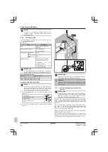
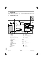
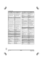
Daikin Altherma 3 GEO Installation Manual Download Page 31

7 Commissioning

Installation manual

31

EGSAH/X06+10DA9W(G)
Daikin Altherma 3 GEO
4P569811-1 – 2019.02

7

Commissioning

NOTICE

NEVER  operate  the  unit  without  thermistors  and/or
pressure  sensors/switches.  Burning  of  the  compressor
might result.

INFORMATION

The  software  is  equipped  with  an  "installer-on-site"  mode
([9.G]: 

Disable  protections

),  that  disables  automatic

operation  by  the  unit.  At  first  installation,  setting 

Disable

protections

  is  by  default  set  to 

Yes

,  meaning  automatic

operation  is  disabled.  All  protective  functions  are  then
disabled. If the user interface home pages are off, the unit
will  NOT  operate  automatically.  To  enable  automatic
operation  and  the  protective  functions,  set 

Disable

protections

 to 

No

.

36 hours after the first power-on, the unit will automatically
set 

Disable protections

 to 

No

, ending "installer-on-site"

mode  and  enabling  the  protective  functions.  If  –  after  first
installation  –  the  installer  returns  to  the  site,  the  installer
has to set 

Disable protections

 to 

Yes

 manually.

NOTICE

Make  sure  that  both  the  domestic  hot  water  tank  and  the
space heating circuit are filled before turning on the power
of the unit.

If  not  filled  before  turning  on  power,  and  in  case

Emergency

  is  active,  the  backup  heater  thermal  fuse  may

blow. To avoid breakdown of the backup heater, fill the unit
before turning on power.

7.1

Checklist before commissioning

After the installation of the unit, first check the following items. Once
all  below  checks  are  fulfilled,  the  unit  MUST  be  closed,  ONLY  then
can the unit be powered up.

You  read  the  complete  installation  instructions,  as
described in the 

installer reference guide

.

The 

indoor unit

 is properly mounted.

The following 

field wiring

 has been carried out according

to this document and the applicable legislation:

▪ Between the local supply panel and the indoor unit

▪ Between the indoor unit and the valves (if applicable)

▪ Between  the  indoor  unit  and  the  room  thermostat  (if

applicable)

The  system  is  properly 

earthed

  and  the  earth  terminals

are tightened.

The 

fuses

  or  locally  installed  protection  devices  are

installed according to this document, and have NOT been
bypassed.

The 

power  supply  voltage

  matches  the  voltage  on  the

identification label of the unit.

There  are  NO 

loose  connections

  or  damaged  electrical

components in the switch box.

There  are  NO 

damaged  components

  or 

squeezed

pipes

 on the inside of the indoor unit.

Backup  heater  circuit  breaker

  F1B  (field  supply)  is

turned ON.

The  correct  pipe  size  is  installed  and  the 

pipes

  are

properly insulated.

There  is  NO 

water  and/or  brine  leak

  inside  the  indoor

unit.

There are no 

odour traces

 noticeable of the used brine.

The 

air purge

 valve is open (at least 2 turns).

The 

pressure relief valve

 purges water when opened.

The 

shut-off valves

 are properly installed and fully open.

The 

domestic hot water tank

 is filled completely.

The 

brine circuit 

and

 water circuit 

are filled correctly.

NOTICE

When the brine circuit is not ready to be used, the system
can  be  set  to 

HP  forced  off

  mode.  To  do  this,  set

[9.5.2]=1 (

HP forced off

 = 

enabled

).

Space  heating  and  domestic  hot  water  are  then  provided
by  the  backup  heater.  Cooling  is  NOT  possible  when  this
mode is active. All commissioning related to or making use
of the brine circuit should NOT be performed until the brine
circuit is filled and 

HP forced off

 is deactivated.

7.2

Checklist during commissioning

To perform an 

air purge

 on the water circuit.

To  perform  an 

air  purge  on  the  brine  circuit

  via  brine

pump test run or 10-day brine operation function.

To perform a 

test run

.

To perform an 

actuator test run

.

Underfloor screed dryout function

The  underfloor  screed  dryout  function  is  started  (if
necessary).

To start 

10-day brine pump operation.

7.2.1

To perform an air purge on the water
circuit

1

Set the user permission level to Installer. See 

"To

change the user permission level" on page 24

.

2

Go to [A.3]: 

Commissioning

 > 

Air purge

.

3

Select 

OK

 to confirm.

Result: 

The air purge starts. It stops automatically

when air purge cycle is finished.

To stop the air purge manually:

1

Go to 

Stop air purge

.

2

Select 

OK

 to confirm.

Summary of Contents for Altherma 3 GEO

Page 1: ...Installation manual Daikin Altherma 3 GEO English Installation manual Daikin Altherma 3 GEO EGSAH06DA9W EGSAH10DA9W EGSAX06DA9W G EGSAX10DA9W G ...

Page 2: ...ν των de acordo com o previsto em в соответствии с положениями 10 11 12 13 14 15 16 17 18 under iagttagelse af bestemmelserne i enligt villkoren i gitt i henhold til bestemmelsene i noudattaen määräyksiä za dodržení ustanovení předpisu prema odredbama követi a z zgodnie z postanowieniami Dyrektyw în urma prevederilor 19 20 21 22 23 24 25 ob upoštevanju določb vastavalt nõuetele следвайки клаузите ...

Page 3: ...uurin sallittu lämpötila TS TSmin Alhaisin matalapainepuolen lämpötila L C TSmax Suurinta sallittua painetta PS vastaava kyllästyslämpötila M C Kylmäaine N Varmuuspainelaitteen asetus P bar Valmistusnumero ja valmistusvuosi katso mallin nimikilpi Maximální přípustný tlak PS K bar Minimální maximální přípustná teplota TS TSmin Minimální teplota na nízkotlaké straně L C TSmax Saturovaná teplota odpo...

Page 4: ... Router 21 5 14 4 Electricity meter 22 5 14 5 Solar inverter energy management system 22 6 Configuration 23 6 1 Overview Configuration 23 6 1 1 To access the most used commands 24 6 2 Configuration wizard 24 6 2 1 Configuration wizard Language 24 6 2 2 Configuration wizard Time and date 24 6 2 3 Configuration wizard System 24 6 2 4 Configuration wizard Backup heater 26 6 2 5 Configuration wizard M...

Page 5: ...A IE 1 g a Shut off valve with integrated filter b Safety valve connection parts for mounting on top of brine level vessel included c Brine level vessel d Remote outdoor sensor with installation manual e Cable for remote outdoor sensor 40 m f O rings spares for hydro module shut off valves g Energy label h General safety precautions i Addendum book for optional equipment j Installation manual k Op...

Page 6: ...ce and repair comply with instructions from Daikin and with applicable legislation for example national gas regulation and are executed only by authorised persons 3 2 Opening and closing the unit 3 2 1 To open the indoor unit NOTICE For a standard installation it is usually NOT required to open the unit Opening the unit or any of the switch boxes is ONLY required when you want to install extra opt...

Page 7: ...rtation of the unit or for servicing The removal of the module will significantly reduce the weight of the unit This makes the unit easier to handle and carry 1 Open the following see 3 2 1 To open the indoor unit on page 6 1 User interface panel 2 1 2 Front panel 2 Remove the insulation from the shut off valves by unfixing the velcro straps on the back of the valves 3 Remove the clips that lock t...

Page 8: ...f valves by turning the lever handles before uncoupling the piping 4 2 Before sliding out the module drain remaining water and brine from the hydro module Open the water and brine air purge valves at the top of the module to speed up the draining process d c a b a Water drain valve b Brine drain valve c Brine air purge valve d Water air purge valve 3 2 3 To close the indoor unit 1 If applicable re...

Page 9: ...e brine circuit Do NOT use Zn coated piping as this may lead to excessive corrosion See also 4 2 4 To fill the brine circuit on page 10 4 1 1 To check the water volume and flow rate of the space heating circuit and brine circuit Minimum water volume Check that the total water volume per circuit in the installation is minimum 20 litre the internal water volume of the indoor unit NOT included INFORM...

Page 10: ...manual of the brine filling kit 4 2 4 To fill the brine circuit WARNING Before during and after filling carefully check the brine circuit for leakage INFORMATION The materials used in the brine circuit of the unit are chemically resistant to the following anti freeze fluids 40 mass propylene glycol 29 mass ethanol 1 Install the brine filling kit See 4 2 3 To connect the brine filling kit on page 1...

Page 11: ...th the applicable legislation NOTICE Air in the water circuit can cause malfunctioning of the backup heater During filling it may not be possible to remove all the air from the circuit Remaining air will be removed through the automatic air purge valves during the initial operating hours of the system Additional filling with water afterwards may be required To purge the system use the special func...

Page 12: ...5 11 To connect the power consumption digital inputs on page 18 Safety thermostat See 5 12 To connect the safety thermostat normal closed contact on page 19 Brine low pressure switch See 5 13 To connect the brine low pressure switch on page 19 LAN adapter connections See 5 14 LAN adapter on page 20 Item Description Room thermostat wired or wireless See Installation manual of the room thermostat wi...

Page 13: ...tial kWh rate power supply without separate normal kWh rate power supply b C1 C2 X5M C1 Preferential kWh rate power supply 3N or 1N C2 Preferential kWh rate power supply contact 1 3 2 Layout Open the unit a 4 Preferential kWh rate power supply with separate normal kWh rate power supply b C1 C2 C3 X5M Z1F X2M C1 Preferential kWh rate power supply 3N or 1N C2 Preferential kWh rate power supply conta...

Page 14: ...ferential kWh rate power supply contact 16 V DC detection voltage supplied by PCB The voltage free contact shall ensure the minimum applicable load of 15 V DC 10 mA Connect the preferential kWh rate power supply contact S1S as follows 2 1 X5M 1 9 10 S1S INFORMATION The preferential kWh rate power supply contact is connected to the same terminals X5M 9 10 as the safety thermostat It is only possibl...

Page 15: ...nal temperature sensor cable to the indoor unit a c d b a Factory mounted cable b Splicing connectors field supply c Remote outdoor sensor cable 40 m delivered as accessory d Remote outdoor sensor delivered as accessory 2 Fix the cable with cable ties to the cable tie mountings 3 Install the remote outdoor sensor outside as described in the installation manual of the sensor delivered as accessory ...

Page 16: ... continuous 9 2 2 DHW pump 9 2 3 DHW pump schedule 1 Open the following see 3 2 1 To open the indoor unit on page 6 1 Top panel 1 3 2 2 User interface panel 3 Installer switch box cover 2 Connect the domestic hot water pump cable to the appropriate terminals as shown in the illustration below 1 M M2P 1 2 X2M 1 1 2 3 Fix the cable with cable ties to the cable tie mountings 5 8 To connect the alarm ...

Page 17: ...page 6 1 Top panel 3 2 5 1 4 2 User interface panel 3 Front panel 4 Installer switch box cover 5 Main switch box cover 2 Connect the alarm output cable to the appropriate terminals as shown in the illustration below Make sure to put wires 2 and 3 between the installer switch box and main switch box in a cable sleeve field supply so that they are double insulated 14a 21 YC Y2 X2M 1 2 3 2 A4P b a 1 ...

Page 18: ...onnect the changeover to external heat source cable to the appropriate terminals as shown in the illustration below 1 2 X2X1 L N X2 X1 a a Installation of EKRP1HB is required 3 Fix the cable with cable ties to the cable tie mountings 5 11 To connect the power consumption digital inputs Wires 2 per input signal 0 75 mm Power limitation digital inputs 12 V DC 12 mA detection voltage supplied by PCB ...

Page 19: ...tion In any case to prevent unnecessary tripping of the safety thermostat it is recommended that the safety thermostat is automatically resettable the safety thermostat has a maximum temperature variation rate of 2 C min there is a minimum distance of 2 m between the safety thermostat and the 3 way valve INFORMATION After it is installed do NOT forget to configure the safety thermostat Without con...

Page 20: ...gration of the heat pump system in a Smart Grid application Components PCB X1A X2A X3A X4A b a LD1 LD2 LD3 LD4 X1A X4A Connectors a DIP switch b Status LEDs Status LEDs LED Description Behaviour LD1 Indication of power to the adapter and of normal operation LED flashing normal operation LED NOT flashing no operation LD2 Indication of TCP IP communication with the router LED ON normal communication...

Page 21: ...utside of the unit which is coming from X4A 50 100 m a Electricity meter X2A 0 75 1 25 mm2 2 b 100 m Solar inverter energy management system 230 V AC detection voltage X1A 0 75 1 5 mm2 Depends on application c 100 m a Ethernet cable Respect the maximum allowed distance between LAN adapter and router which is 50 m in case of Cat5e cables and 100 m in case of Cat6 cables b These wires MUST be sheath...

Page 22: ...on page 6 1 Top panel 3 1 2 4 2 User interface panel 3 Front panel 4 Main switch box cover 2 Connect the electricity meter to LAN adapter terminals X2A 1 2 1 2 S1S 1 2 2 1 INFORMATION Mind the polarity of the cable The positive wire MUST be connected to X2A 1 the negative wire to X2A 2 WARNING Make sure to connect the electricity meter in the correct direction so that it measures the total energy ...

Page 23: ...re copper wire CANNOT be visible 1 3 2 1 Open the following see 3 2 1 To open the indoor unit on page 6 1 Top panel 3 1 2 4 2 User interface panel 3 Front panel 4 Main switch box cover 2 Provide a detection voltage to X1A N L Make sure X1A N L are protected by a fast acting circuit breaker 100 mA 6 A type B 3 For the system to run in the Recommended ON operation mode Smart Grid application connect...

Page 24: ...ing Example Modify 1 01 from 15 to 20 Most settings can be configured via the menu structure If for any reason it is required to change a setting using the overview settings then the overview settings can be accessed as follows 1 Set the user permission level to Installer See To change the user permission level on page 24 2 Go to 9 I Installer settings Overview field settings 3 Turn the left dial ...

Page 25: ...duced DHW off space heating is reduced and domestic hot water is NOT available auto SH normal DHW off space heating operates as normally but domestic hot water is NOT available Similarly as in Manual mode the unit can take the full load with the backup heater if the user activates this via the Malfunctioning main menu screen To keep energy consumption low we recommend to set Emergency to auto SH r...

Page 26: ...ng the heat up cool down cycle The target delta T for the main zone depends on this setting In room thermostat control Emitter type influences the maximum modulation of the desired leaving water temperature and the possibility for usage of the automatic cooling heating changeover based on the indoor ambient temperature It is important to set Emitter type correctly and in accordance with your syste...

Page 27: ...ally increase the leaving water temperature for all ambient temperatures Slope offset WD curve example screens Weather dependent curve when slope is selected X1 X2 c d e Y1 Y2 Y3 Y4 a b Weather dependent curve when offset is selected Y1 Y2 Y3 Y4 X1 X2 a b c d e Possible actions on this screen Select slope or offset Increase or decrease the slope offset When slope is selected set slope and go to of...

Page 28: ...setpoint The storage economic temperature denotes the lower desired tank temperature It is the desired temperature when a storage economic action is scheduled preferably during day Code Description 5 3 6 0B Eco setpoint 30 C min 50 6 0E C Reheat setpoint Desired reheat tank temperature used in Schedule reheat mode during reheat mode the guaranteed minimum tank temperature is set by the Reheat setp...

Page 29: ...n a certain application is 2 C then the unit freeze up prevention limit temperature MUST be set to 12 C or lower Result will be that the brine mixture may NOT freeze above that temperature To prevent freezing of the unit check the type and concentration of the brine carefully Code Description 9 M A 04 Brine freezing temperature 0 2 C 1 2 C 2 4 C 3 6 C 4 9 C 5 12 C 6 15 C 7 18 C NOTICE The Brine fr...

Page 30: ...Voltage Configuration Maximum capacity Equilibrium Equilibrium temperature Operation 9 6 Balancing Space heating priority Priority temperature Minimum running timer Anti recycle timer Maximum running timer Additional timer 9 8 Benefit kWh power supply Benefit kWh power supply Allow heater Allow pump 9 9 Power consumption control Power consumption control Type Limit Limit 1 Limit 2 Limit 3 Limit 4 ...

Page 31: ...able The system is properly earthed and the earth terminals are tightened The fuses or locally installed protection devices are installed according to this document and have NOT been bypassed The power supply voltage matches the voltage on the identification label of the unit There are NO loose connections or damaged electrical components in the switch box There are NO damaged components or squeez...

Page 32: ... 2 Commissioning Actuator test run 3 Select a test from the list Example Pump 4 Select OK to confirm Result The actuator test run starts It stops automatically when done 30 min for Pump 120 min for Brine pump 10 min for other test runs To stop the test run manually 1 Go to Stop test run 2 Select OK to confirm Possible actuator test runs Backup heater 1 test 3 kW capacity only available when no cur...

Page 33: ...oning menu 1 Set the user permission level to Installer See To change the user permission level on page 24 2 Go to A 6 Commissioning 10 day brine pump operation 3 Select On to start the 10 day brine pump operation Result The 10 day brine pump operation starts During the 10 day brine pump operation the setting will be displayed as ON in the menu Once the procedure has been completed it will change ...

Page 34: ... Ø22 mm c1 Brine IN Ø28 mm c2 Brine OUT Ø28 mm d Shut off valve e Automatic air purge valve f Safety valve g Shut off valve h Manual air purge valve i Drain valve j Backup heater k Recirculation connection 3 4 G female l Check valve m Muffler n Refrigerant pressure relief valve o Service port p Heat sink q Filter r Rectifier s Plate heat exchanger Refrigerant flow Heating Cooling B1L Flow sensor B...

Page 35: ...CB A3P On OFF thermostat A3P Heat pump convector A4P Digital I O PCB A4P Receiver PCB Wireless On OFF thermostat PC power circuit A6P Backup heater control PCB A7P Inverter PCB A8P Demand PCB A15P LAN adapter A16P ACS digital I O PCB CN A4P Connector CT Current sensor DS1 A8P DIP switch F1B Overcurrent fuse F1U F2U A4P Fuse 5 A 250 V F2B Overcurrent fuse compressor K R A4P Relay on PCB K9M Thermal...

Page 36: ...ical meters Electricity meters For safety thermostat For safety thermostat Inrush Inrush current Max load Maximum load Normally closed Normally closed English Translation Normally open Normally open Safety thermostat contact 16 V DC detection voltage supplied by PCB Safety thermostat contact 16 V DC detection voltage supplied by PCB Shut off valve Shut off valve SWB Switch box 7 Option PCBs 7 Opti...

Page 37: ...ial kWh rate unit power supply installation Only with EKGSPOWCAB Compressor power supply 230 V earth Only with EKGSPOWCAB POWER SUPPLY FIELD SUPPLY OPTIONAL PART Only for EKCSENS INDOOR UNIT STANDARD PARTS Alarm output Changeover to external heat source output Only for EKRP1HB Note In case of signal cable keep minimum distance to power cables 5 cm FIELD SUPPLY Space heating On OFF output NO valve ...

Page 38: ......

Page 39: ......

Page 40: ...4P569811 1 2019 02 Copyright 2019 Daikin 4P569811 1 0000000S ...

Reviews: