


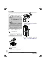


5 Electrical installation
Installation manual
14
EGSAH/X06+10DA9W(G)
Daikin Altherma 3 GEO
4P569811-1 – 2019.02
a
b
Q1DI
L1 L2 L3 N
3N~, 50 Hz, 400 V AC
F1B
1
3
5
7
2
4
6
8
I
I
I
I
Q1DI
L
N
1N~, 50 Hz, 230 V AC
F1B
1
3
5
7
2
4
6
8
I
I
I
I
1N~
3N~
OR
BRN
BLK
G
RY
BLU
YL
W/GRN
BRN
BLK
G
RY
BLU
YL
W/GRN
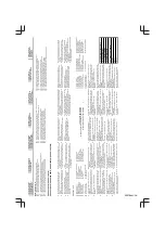
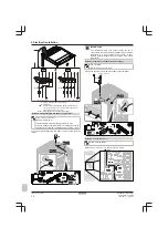
a
Factory-mounted power supply cable
b
Field wiring
F1B
Overcurrent fuse (field supply). Recommended fuse for
1N~: 4‑pole, 32 A fuse, C curve. Recommended fuse for
3N~: 4‑pole, 16 A fuse, C curve.
Q1DI
Earth leakage circuit breaker (field supply)
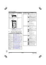
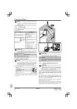
Detail C2: Preferential kWh rate power supply contact
Wires: 2×(0.75~1.25 mm²)
Maximum length: 50 m.
Preferential kWh rate power supply contact: 16 V DC
detection (voltage supplied by PCB). The voltage-free contact
shall ensure the minimum applicable load of 15 V DC, 10 mA.
Connect the preferential kWh rate power supply contact (S1S) as
follows.
2×
1×
X5M
1×
9 10
S1S
INFORMATION
The preferential kWh rate power supply contact is
connected to the same terminals (X5M/9+10) as the safety
thermostat. It is only possible for the system to have
EITHER preferential kWh rate power supply OR a safety
thermostat.
Detail C3: Separate normal kWh rate power supply
Wires: 1N+GND
Maximum running current: 6.3 A
Connect the separate normal kWh rate power supply as follows:
Q3DI
L N
1N~, 50 Hz, 230 V AC
1×
2×
X2M
1×
5 6
L N
Detail C4: Connection of
X11Y
Factory-mounted cables.
Disconnect X11Y from X11YA, and connect it to X11YB.
Z1F
X11YA
X11YB
X2M/5+6
X11Y
Summary of Contents for Altherma 3 GEO
Page 38: ......
Page 39: ......
Page 40: ...4P569811 1 2019 02 Copyright 2019 Daikin 4P569811 1 0000000S ...


