background image

14

Configuration Mode

The configuration mode is used to set the thermostat to match your heating/cooling system. The thermostat functions with heat 
pump, air conditioning, gas, oil, or electric heat systems. To configure the thermostat, perform the following steps:

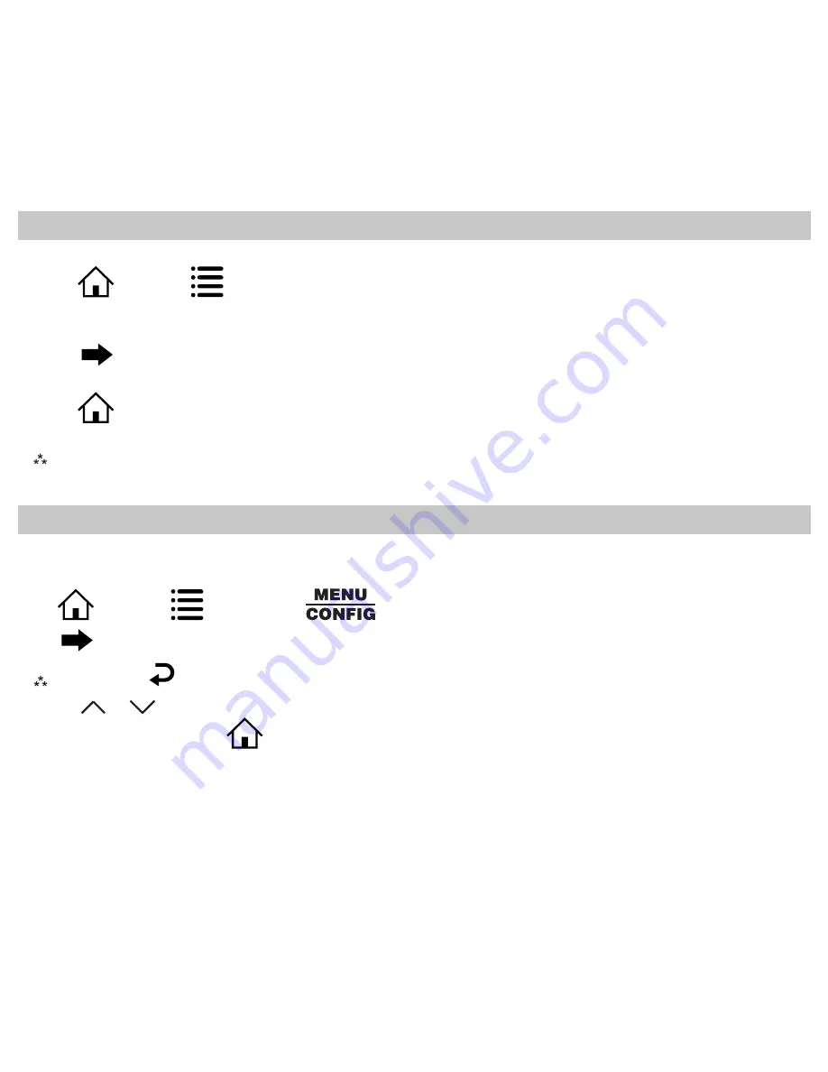
Press 

, then press 

 repeatedly until 

 is selected. 

Press  

  to advance from one screen to the next. 


Note: 

Pressing


will return you to the previous screen.

Press the 

 or 


 to change settings within each screen. Changes are saved automatically.

To exit configuration mode, press 

Auto exit occurs after two minutes with no icons touched.

To change the lock code, do the following:

1.  Press 

, then press 

 until Lock menu displays.

2.  Enter the current lock codes. To find the current lock codes, follow the instructions under “Configuration and Thermostat 

Lock”.

3.  Press  

  to enter new lock codes.

4.  Enter new lock codes.

5.  Press 

. The Lock Codes have been updated.


Note: 

Upon subsequent power ups, new lock codes will display.

Changing the Lock Code

Summary of Contents for 910193131

Page 1: ...ctable Fahrenheit or Celsius Icon Indicator Lights Relay Outputs Minimum Voltage Drop in Thermostat WSHP Alarm Indicator Remote Sensor Compatible Ideally Suited for Residential New Construction Replac...

Page 2: ...ctrical Rating 24 VAC 18 30 VAC 1 amp maximum per output terminal 5 amp maximum total load Temperature Control Range 45 F to 90 F 7 C to 32 C Accuracy 1 F 0 5 C Anti short Cycle 4 minutes bypass anti...

Page 3: ...he compressor come on for 4 minutes after it turns off to protect your compressor When the room temperature is greater than the set cool temperature by the differential temperature the cooling device...

Page 4: ...t is in Setup Mode and is searching for a wireless network Flashing Wi Fi is busy Solid The thermostat is not connected to Wi Fi If the thermostat has successfully connected to Wi Fi previously and no...

Page 5: ...screws to secure wires CAUTION Be sure exposed portion of wires do not touch other wires 9 Gently tug wire to be sure of proper connection Double check that each wire is connected to the proper termin...

Page 6: ...nsor W1 1st stage heat W2 2nd stage heat W3 3rd stage heat Y1 1st stage cool Y2 2nd stage cool Y3 3rd stage cool Note 1 Not all terminals are used in every model Note 2 A connection to 24VAC common C...

Page 7: ...1 Y2 Y1 G C RH RC W2 G2 A PROGRAMMABLE TOUCH SCREEN MICROTECH III CONTROLLER TERMINAL TB2 TERMINAL STRIP G2 910193130 W2 W1 Y2 Y1 G C R A W1 Y2 Y1 G C RH RC W2 G2 A PROGRAMMABLE TOUCH SCREEN MICROTECH...

Page 8: ...1 Y2 Y1 G C RH RC W2 A PROGRAMMABLE TOUCH SCREEN MICROTECH III CONTROLLER TERMINAL TB2 910193132 Y1 I O EXPANSION MODULE TB1 1 W1 Y2 Y1 G C RH RC W2 A PROGRAMMABLE TOUCH SCREEN MICROTECH III CONTROLLE...

Page 9: ...9 Wiring Diagrams continued W1 Y2 Y1 G C RH RC W2 A PROGRAMMABLE TOUCH SCREEN MICROTECH III CONTROLLER TERMINAL TB2 910193134 DH I O EXPANSION MODULE TB1 1 W2 W1 Y2 Y1 G C R A...

Page 10: ...ng 2 Select an appropriate location for mounting the remote sensor 3 Mount the remote sensor using hardware provided 4 Install two strand shielded wire between the S1 terminal on the remote sensor and...

Page 11: ...ressors Y1 G O Y1 Y2 G O Y1 G B Y1 Y2 G B Heat Pump Two Compressors w High Speed Fan Y1 G2 O Y1 Y2 G2 O Y1 G2 B Y1 Y2 G2 B 910193131 Output Chart 1st Cool 2nd Cool 1st Heat 2nd Heat Water Source Heat...

Page 12: ...ors Y1 G O Y1 Y2 G O Y1 G B Y1 Y2 G B Y1 Y2 W2 G B 910193134 Output Chart 1st Cool 2nd Cool 1st Heat 2nd Heat Water Source Heat Pump Y1 G Y1 Y2 G W1 W1 W2 Electric Y1 G Y1 Y2 G W1 G W1 W2 G Heat Pump...

Page 13: ...diagram is the code that will unlock the desired configuration setting The smaller numbers indicated by 93 and 82 in the diagram are codes used to lock and unlock your thermostat to prevent tampering...

Page 14: ...the previous screen Press the or to change settings within each screen Changes are saved automatically To exit configuration mode press Auto exit occurs after two minutes with no icons touched To chan...

Page 15: ...the or to set differential value Press to advance to the next screen CONFIG 3 2nd Stage Temperature Differential 1 F to 5 F 0 5 C to 2 5 C Set the number of degrees between when stage 1 turns on and w...

Page 16: ...is set to Press the or to set Press to advance to the next screen CONFIG 7 Heat Source There are six heat source settings WARNING Incorrect settings can damage system and or cause potentially dangero...

Page 17: ...ance to the next screen CONFIG HEAT 11 Minimum Cool Setpoint 45 F to 90 F 7 C to 32 C Adjust to control the minimum cool set temperature allowed Press the or to select Press to advance to the next scr...

Page 18: ...no remote sensor option 1 L must be selected May only be used with remote temperature sensor 1 CONFIG Appears only for non heat pump systems and heat pumps without an outdoor sensor 1 L Only on board...

Page 19: ...he dehumidifier to turn on Press or to select Press to advance to the next screen CONFIG HUMIDITY RH 19 Humidity Differential 1 to 10 Set the percent difference between the setpoint humidity and when...

Page 20: ...o select Press to advance to the next screen CONFIG ON SCHEDULE FAN OFF 22 Relay Operation dehumidification only Set the relay function to match your system normally open normally closed Press or to s...

Page 21: ...connect to the wireless network for the first time If you have previously connected the thermostat to the wireless network but have changed your password or installed a new wireless router you will h...

Page 22: ...1 Without closing the Dakin App open phone s settings 2 Choose connections 3 Select Wi Fi 4 Select the thermostat s ID from the list of available networks thermostat ID s will begin with I3_ 5 Once co...

Page 23: ...8 Press to save value and move to hour 9 Press or to select the hour Note As you move past 12 00 the AM PM symbol will change automatically 10 Press to save the value and move to minutes 11 Press or...

Page 24: ...HEAT HEAT MODE The possible operating modes for the thermostat are OFF HEAT EM HEAT COOL and AUTO Use to select Auto Mode In this mode the thermostat controls either heating or cooling systems automat...

Page 25: ...reen shows exclusively the current fan setting AUTO ON HOURLY and current fan speed HI LOW The FAN UP and DOWN buttons are enabled ON FAN Hi ON FAN Hi HOURLY FAN Hi AUTO FAN Hi Press icon fan setting...

Page 26: ...n the FAN screen above ON SCHEDULE FAN COOL MODE PM ON Tue COOL Fan speed set for either mode will apply to all modes For example speed set to HI on AUTO mode will apply to ON and HOURLY mode If detai...

Page 27: ...screen The icons will not flash in sleep mode Press the button the home screen will flash either the icon or the icon The number of flashes indicates the current stages of cooling or heating ON SCHEDU...

Page 28: ...s displayed 2 Adjust set temperature so it is 5 degrees below room temperature 3 Cooling should come on within a few seconds 4 Adjust the set temperature 2 degrees above the room temperature and the c...

Page 29: ...ash Use the or to select the minutes when you want the current period to begin 10 Press to continue 11 The HEAT temperature flashes Use the or to set the desired heat temperature 12 Press to continue...

Page 30: ...ure if not used VIEW Remote Sensor VIEW View if locked or unlocked Unlocked Locked VIEW Day Month Year View month day and year VIEW View filter status Accumulated fan run time displays VIEW SLEEP Disp...

Page 31: ...addition if selected the schedule can be overridden only until the next transition period To access the Schedule override feature enter the screen then use to scroll through the menu options until you...

Page 32: ...The thermostat comes pre programmed with the following schedule TUESDAY 2 WAKE LEAVE RETURN SLEEP HEAT HEAT HEAT HEAT COOL COOL COOL COOL WEDNESDAY 3 WAKE LEAVE RETURN SLEEP HEAT HEAT HEAT HEAT COOL C...

Page 33: ...o auto is continuous run Room temperature is not correct Calibrate thermostat see Configuration Mode Setting If remote sensor is used check S1 and SC terminal connections LOCK displays when any button...

Page 34: ...eat or cool mode on the thermostat by the temperature differential Setpoints do not display all of the time Press MENU VIEW six times Problem finding app Apple devices require iOS 7 0 or newer softwar...

Page 35: ...storage incorrect installation or servicing not performed by the Seller In order to permit the Seller to properly administer the warranty the Buyer shall 1 Notify the Seller promptly of any claim sub...

Page 36: ...quivalent isotropically radiated power e i r p is not more than that necessary for successful communication Conform ment la r glementation d Industrie Canada le pr sent metteur radio peut fonctionner...

Reviews: