ENGLISH
12
5. MANAGEMENT
5.1 Storage
All the pumps must be stored indoors, in a dry, vibration-
free and dust-free environment, possibly with constant
air humidity.
They are supplied in their original packaging and must
remain there until the time of installation. If this is not
possible, the intake and delivery aperture must be
accurately closed.
5.2 Transport
Avoid subjecting the electropumps to needless jolts or
collisions. The figures below indicate respectively how to
lift single electropumps – Fig. 5A-6A-7 pag.82– and twin
versions – Fig. 5B-6B-7 pag.82 – during installation,
after they have been removed from the packaging
.
5.3 Weights
The adhesive label on the package indicates the total
weight of the electropump.
6. WARNINGS
6.1 Safety
Use is allowed only if the electric system is in
possession of safety precautions in accordance with the
regulations in force in the country where the product is
installed (for Italy, CEI 64/2).
6.2 Checking motor shaft rotation
Before installing the pump you must check that the
rotating parts turn freely. For this purpose, proceed as
follows on the pump concerned
: remove the fan cover
from its seat in the motor end cover, loosening the nuts.
Move the fan by hand to turn the motor shaft a few
times. If this is not possible, dismantle the pump body,
slackening the screws to check whether there are any
foreign bodies inside it. To disassemble, proceed in the
inverse order to assembly.
Do not force the fan with pliers or
other tools to try to free the pump as
this could cause deformation or
breakage of the pump.
6.3 New systems
Before running new systems the valves, pipes, tanks
and couplings must be cleaned accurately. Often
welding waste, flakes of oxide or other impurities fall off
after only a certain period of time. To prevent them from
getting into the pump they must be caught by suitable
filters. The free surface of the filter must have a section
at least 3 times larger than the section of the pipe on
which the filter is fitted, so as not to create excessive
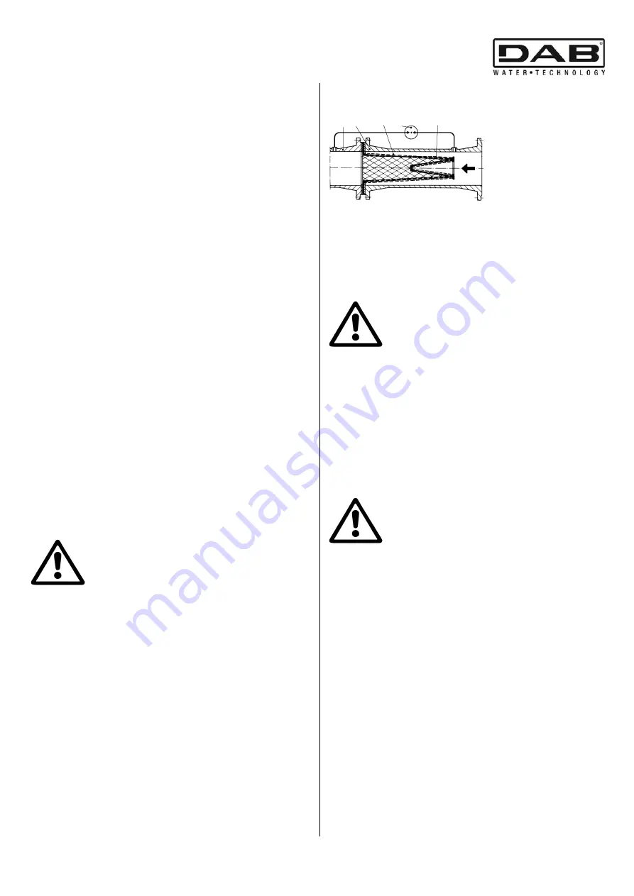
load losses. We recommend the use of TRUNCATED
CONICAL filters made of corrosion-resistant materials
(SEE DIN 4181):
Fig. 3
5 1 2 4
3
1
-Filter body
2-Narrow mesh filter
3-
Differential pressure gauge
4-Perforated sheet
5-Pump intake aperture
7. PROTECTIONS
7.1 Moving parts
In accordance with accident-prevention regulations, all
moving parts (fans, couplings, etc.) must be accurately
protected with special devices (fan covers,ecc.) before
operating the pump.
During pump operation, keep well away
from the moving parts (shaft, fan, etc.)
unless it is absolutely necessary, and only then
wearing suitable clothing as required by law, to avoid
being caught.
7.2 Noise level
The noise levels of pumps with standard supply motors are
indicated in table A on page 76.
Remember that, in cases where the LpA noise levels
exceed 85 Db(A), suitable HEARING PROTECTION must
be used in the place of installation, as required by the
regulations in force.
7.3 Hot and cold parts
DANGER OF BURNING
!!
As well as being at high temperature and
high pressure, the fluid in the system may
also be in the form of steam
!
It may be dangerous even to touch the pump or parts
of the system.
If the hot or cold parts are a source of danger, they must
be accurately protected to avoid contact with them
.
8. INSTALLATION
To protect the pump against deposits, it is advisable to
install it in the lowest point of the system. Fit the pump
in the plant only after having completed the welding
works and checked that the plant is quite clean.
The electropump must be fitted in a well ventilated
place, protected from unfavourable weather conditions
and with an environment temperature not exceeding
40°C.
(Fig.B)
.
Electropumps with degree of protection
IP55 may be installed in dusty and damp
environments. If installed in the open, generally it is
not necessary to take any particular steps to protect
them against unfavourable weather conditions.
Summary of Contents for CM-G
Page 2: ...P 7 5 kW P 7 5 kW...
Page 43: ...38 C 8 9 77 B 76 D 10 E F 5 G 11 30 5 5 20 30 7 5 60 5 10 11 1 0 C...
Page 44: ...39 12 IP55 12 1 12 2 4 Fig 4 13...
Page 45: ...40...
Page 78: ...73 C 8 9 3 D 3 10 E 3 F 5 G 11 1 30 3 5 5 HP 20 30 3 7 5 60 HP 5 10 11 1 0 C...
Page 79: ...74 12 12 1 12 2 4 Fig 4 13 The pump supplies insufficient flow 3...
Page 80: ...75...
Page 90: ...85...
Page 91: ...86...


