D-Link DCS-6315, User Manual
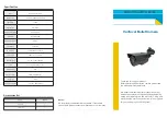
The D-Link DCS-6315 is a high-quality surveillance camera that guarantees advanced security features. To ensure a hassle-free setup, refer to the Quick Installation Manual, available for free download at manualshive.com. This comprehensive manual provides step-by-step instructions to assist you in maximizing the potential of your DCS-6315 camera.
Share
Download


Reviews:
No comments
Related manuals for DCS-6315

1130
Brand: Data Harvest Pages: 19

ES-HNG200I-EI
Brand: Vertiv Pages: 16

MEGApix DWC-MV82WiA
Brand: Digital Watchdog Pages: 2

MIP SYSTEM 3 B7835
Brand: LLOYTRON Pages: 12

H2iQ Series
Brand: Watts Pages: 10

SK-V207IR-Z946
Brand: Huviron Pages: 56

MVA-1000
Brand: NAPCO Pages: 4

801-G02
Brand: Microgard Pages: 134

vLoc3 RTK-Pro
Brand: Vivax Metrotech Pages: 78

C-AX401D1M
Brand: i3 International Pages: 11

ExCam IPQ6055
Brand: Samcon Pages: 24

GVR102
Brand: QIMMIQ Pages: 87

PEREL EMS108
Brand: Velleman Pages: 4

OB-E400AF
Brand: Brickcom Pages: 19

Elaho
Brand: echoflex Pages: 20
NAC-HD-326VL/60-G
Brand: Navaio Pages: 2

KC440xMP
Brand: Ultrak Pages: 20

FortiCam FD40
Brand: Fortinet Pages: 27


