8
6. OPERATION CONTROLS AND FUNCTIONS
6.1 Front Panel
KEY 1
KEY 6
KEY 11
KEY 2
KEY 7
KEY 12
KEY 3
KEY 8
KEY 13
KEY 4
KEY 9
KEY 14
KEY 5
KEY 10
KEY 15
1
KEY 1
KEY 2
KEY 3
KEY 4
KEY 5
KEY 6
KEY 7
KEY 8
KEY 9
1
1
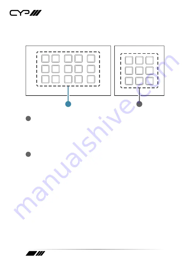
KEY 1~15 (1~9) Buttons:
Each button activates the customizable
macro that has been assigned to it. All buttons contain a pair of
colored LEDs (red and blue) with macro controllable individual
brightness levels from 0~100.
Note: Further details on macro configuration settings please refer to
section 6.4.
2
RESET Pinhole (Hidden behind the wall plate):
Pressing this pinhole
button in combination with various keys will reset different aspects of
the unit to their factory default.
Note: The unit must already be powered on before the buttons are
pressed.
USB firmware update: Plug the USB mass storage device on the USB
port hidden behind the wall plate, press and hold Key 1 and the
pinhole button simultaneously to update the firmware.
Ethernet Reset: Press and hold Key 6 (Key 4 on the 1-gang version)
and the pinhole button simultaneously to reset the unit’s Ethernet
settings to their factory default state.
Keypad LED Default Settings: Press and hold Key 11 (Key 7 on the
1-gang version) and the pinhole button simultaneously to reset the
Keypad LED Default Setting which switch on all blue LED, switch off
all red LED, and demo mode is on.
Summary of Contents for CR-KP1
Page 1: ...OPERATION MANUAL CR KP1 CR KP2 15 or 9 Button Wall Mount Keypad Control Systems...
Page 2: ......
Page 45: ......
Page 46: ......
Page 47: ......


