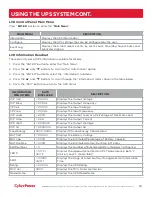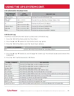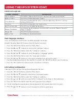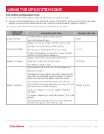
įĂĀĂĀƫ5!.ƫ+3!.ƫ5/0!)/ƫĨĩČƫ *ċƫ((ƫ.%#$0/ƫ.!/!.2! ċƫ((ƫ+0$!.ƫ0. !).'/ƫ.!ƫ0$!ƫ,.+,!.05ƫ+"ƫ0$!%.ƫ.!/,!0%2!ƫ+3*!./ċƫ
20
UPS SYSTEM STARTUP
After completing the hardware installation of the UPS, you are now ready to connect the UPS and connect
your equipment.
To start the UPS:
1. Verify that the UPS input cable or terminal blocks are connected to AC source.
2. Verify that the EBM DC output cable is connected to the UPS DC connector.
3. If UPS has a Maintenance Bypass Switch (MBS), verify that the switch is set to NORMAL
and the Interlock Bracket is secured to right with the yellow screw.
4. Set the EBM DC breaker to “ON” position.
5. Set the UPS input circuit breaker to “ON” position.
6. Set the upstream circuit breaker (not provided) to the “ON” position. The UPS LCD shows “CyberPower”
and fans turn on.
7. Press the ON/OFF button on the UPS front panel for at least 3 seconds to start the UPS.
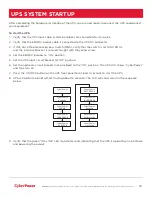
8. UPS will perform a brief self-test lasting about 15 seconds. The LCD will show result in the sequence
below.
9. Verify that the green “ON-LINE” LED illuminates solid, indicating that the UPS is operating in Line Mode
and powering the output.
CyberPower
CyberPower
Ready On
CyberPower
FAN OK
CyberPower
CHARGER OK
CyberPower
DC BUS OK
CyberPower
BATTERY OK
CyberPower
INVERTER OK
CyberPower
Battery Mode
CyberPower
Ready On
CyberPower
Line Mode


