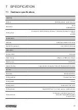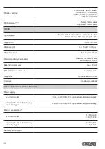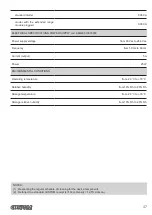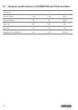
Assembly instructions
NOTE: All the dimensions shown in following igures are in millimetres.
1
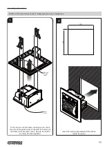
Insert the device assembled with the frame
inside the panel
Fit the device into the frame, making sure to orient
the side of the gears cover at the sled for hooking of
the frame (with beveled corner). Secure the device
by using the clips supplied.
2
113
1
1
3
Gears
cover
Sled with
beveled
corner
59
Summary of Contents for PLUS2
Page 1: ...CUSTOM S p A USER MANUAL PLUS2 ...
Page 2: ......
Page 4: ......
Page 5: ...MANUAL For details on the commands refer to the manual with code 77200000002100 ...
Page 6: ......
Page 10: ...10 ...
Page 15: ...2 5 Key functions standby advance the paper preset length STANDBY Fast push 15 ...
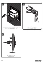
Page 18: ...4 To remove the fixing clips lift the lever shown in figure with a small screwdriver 18 ...
Page 22: ...Model with the 8 42 Vdc extended range module plugged USB Serial RS232 TTL Power supply 22 ...
Page 28: ...28 ...
Page 38: ...38 ...
Page 56: ...56 ...
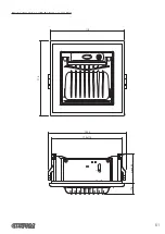
Page 61: ...Device dimensions with the frame assembled 119 max 46 5 17 4 123 2 112x112 119 RS232 TTL 61 ...
Page 62: ...62 ...

