2.6
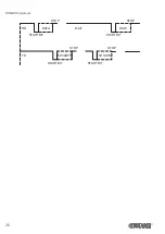
Status led lashes
The status of the device is sent to the serial port. To get a visual feedback of the signallings is necessary to build a cable
to be connected to the serial port (see par. 3.3).
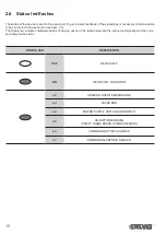
The Status led indicates hardware status of device. Given in the table below are the various led signals and the corre-
sponding device status.
STATUS LED
DESCRIPTION
OFF
DEVICE OFF
ON
DEVICE ON: NO ERROR
x 2
HEADING OVER TEMPERATURE
x 3
PAPER END
x 4
POWER SUPPLY VOLTAGE INCORRECT
x 5
RECEPTION ERRORS
(PARITY, FRAME ERROR, OVERRUN ERROR)
x 6
COMMAND NOT RECOGNIZED
x 7
COMMAND RECEPTION TIME OUT
16
Summary of Contents for PLUS2
Page 1: ...CUSTOM S p A USER MANUAL PLUS2 ...
Page 2: ......
Page 4: ......
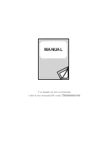
Page 5: ...MANUAL For details on the commands refer to the manual with code 77200000002100 ...
Page 6: ......
Page 10: ...10 ...
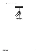
Page 15: ...2 5 Key functions standby advance the paper preset length STANDBY Fast push 15 ...
Page 18: ...4 To remove the fixing clips lift the lever shown in figure with a small screwdriver 18 ...
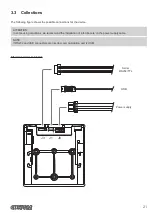
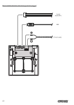
Page 22: ...Model with the 8 42 Vdc extended range module plugged USB Serial RS232 TTL Power supply 22 ...
Page 28: ...28 ...
Page 38: ...38 ...
Page 56: ...56 ...
Page 61: ...Device dimensions with the frame assembled 119 max 46 5 17 4 123 2 112x112 119 RS232 TTL 61 ...
Page 62: ...62 ...


