3
TABLE OF CONTENTS
Machine Specifications1111111111111..11111.111.111..11 5
Major Components Diagram11111111111.1111..1111111..11 6
Forward11111111111111111111..1111111111..111. 7
Description1111111111111111111111111111..111.1..7
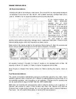
Working Principles 111111111111111111111111.1111.... 8
Fluid Systems Diagram1111111111111111..11.11111111 8-9
Assembly Instructions111111111111111111111111..1.........10
Charging The Battery11111111111111111111111111...10-11
Machine Installation1111111111111111111111..111111 12
Safety Precautions....................................................................................................13-14
Operation........................................................................................................................15
Pre-Spray Check List...........................................................................................16
Engine Reparation...............................................................................................17
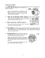
Starting The Engine1111111111111..11.....................................18
Liquid Flowability Measurement.....................................................................19-20
Typical Insecticide Flow Rate..............................................................................21
Particle Size Tables ............................................................................................22
Syncroflow Section....................................................................................................23-24
Maintenance...................................................................................................................25
Maintenance Schedule........................................................................................26
Formulation/Flush Solenoid Valve..................................................................27-28
Formulation Filter.................................................................................................29
Blower Filter.........................................................................................................30
Nozzles...........................................................................................................31-32
3-Way Solenoid Valve..........................................................................................33
Hi-Flex Coupling Installation Instructions1111111.11111...1134-36
Storage And Shipment....................................................................................37-38
Parts Identification1111111111111111111.111..1111..1139
Machine Diagram (Exploded View)11111111.111..11111139-40
Engine Assembly 18 Hp Vanguard1111111111111111111.41
Blower Assembly111111111111111.1111111111...142
Summary of Contents for MAXI-PRO 2D ULV
Page 6: ...6 MAJOR COMPONENTS DIAGRAM ...
Page 9: ...9 ...
Page 39: ...39 ...
Page 43: ...43 BOOM ASSEMBLY MAXI PRO 2D P N 64905 ...
Page 50: ...50 ...


