36
INSTALLATION OF FLEXIBLE ELEMENT
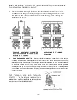
5. You may loosen the flange assembly screws as much as possible without
disassembly of cover or you may remove the screws completely thus disassembling
the cover. In either case wrap the flexible element around the flange assembling.
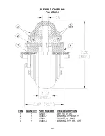
Make sure the beads of the element are fully worked down upon the seats of covers
as shown in the detail on the right drawing. To insure proper seating, rap on the tire
O.D. with a small mallet until the split is closed.
IMPORTANT
: Split must be closed after assembly is completed.
6. Hold with your hand the split of the flexible element. Tighten (finger tight) one or two
screws directly opposite the split. Using both hands knead the tire pulling it toward
the split. Repeat the procedure on all remaining screws. Retighten each screw, in
succession, with a torque wrench to 300 in.-lb.
NOTE : The metal pieces of the coupling that clamp the rubber element will
operate properly only if tightly clamped by the screws. Over tightening cannot
damage the rubber element, but being too loose may damage the coupling.
TO REPLACE TIRE
Loosen all flange assembly screws completely to disengage the covers of the flange
assemblies. Grasp one end of the flexible element at the split and peel it off the flange
assemblies. Remove any foreign substances, such dirt, off both sides of the flange
assemblies and install the new flexible element according to step 5 and 6. If necessary
to replace flange assembly screws, use only grade 8 or equivalent.
IMPORTANT NOTICE: Because of the possible danger to person(s) or property from
accidents which may result in the use of these products, it is important that the Hi-Flex
coupling be used in accordance with the engineering information specified in the catalog
and in these instructions. Proper installation, maintenance and operating procedures
must be observed. Proper guards and other safety devices that may be needed or
specified in safety codes should be provided and used, but are neither provided by, nor
the responsibility of the manufacturer.
Summary of Contents for MAXI-PRO 2D ULV
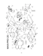
Page 6: ...6 MAJOR COMPONENTS DIAGRAM ...
Page 9: ...9 ...
Page 39: ...39 ...
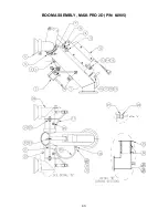
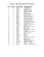
Page 43: ...43 BOOM ASSEMBLY MAXI PRO 2D P N 64905 ...
Page 50: ...50 ...

