HV Breakout Module – Mounting and installation
Installation Manual
24
Version 01.20 // 2021
Pin
Signal
Description
1
5
4 3
2
1
Power +
Power supply, plus
2
Power GND
Power supply, ground
3
CAN_H
CAN high
4
CAN_L
CAN low
5
CAN_GND
CAN ground
Housing
Shield
Cable shield
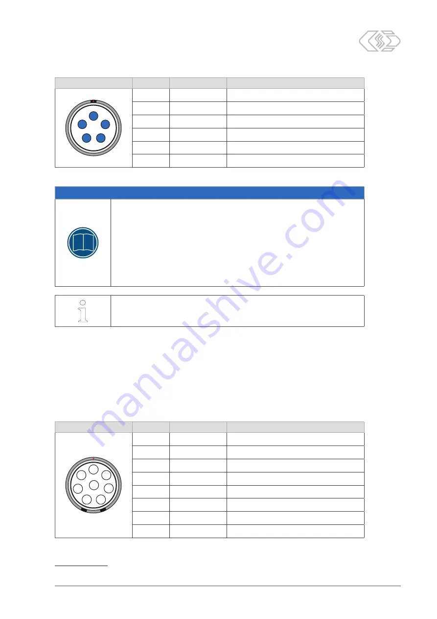
Tab. 4-3: Plug (front view) for CAN socket: Pin assignment
NOTE!
i
The CAN sockets for CAN signals and power supply are connected in par-
allel and have identical pin assignments. The signal applied to a specific
pin is therefore always available at both sockets.
Also, either socket can be used as well for
CAN OUT
as for
CAN IN
purposes.
This enables simple cabling with only one cable between two measurement
modules. At the end of the measurement chain, a CAN termination resistor
is plugged into the open CAN socket.
"
Make sure that this work is only carried out by qualified and trained
personnel.
i
The LEMO 0B socket is CSM's standard version. To equip the measurement
module with other sockets, please contact the sales department.
4.4.2.2 EtherCAT® IN socket
The measurement module is connected to the XCP-Gateway (alternatively to an EtherCAT®
master) or to an upstream EtherCAT® measurement module via the
IN
socket. EtherCAT®
measurement modules receive their power supply from the XCP-Gateway, i.e. via the same
cable connection.
CSM uses LEMO 1B sockets as standard for the
IN
socket. To connect a cable to this socket,
the following plug with socket insert is required:
f
FGL.1B.308.CLL xxxxx
13
Pin
Signal
Description
1 7
6
5
4
3
2
8
1
V
Batt
+
Power supply, plus
2
GND
Ground
3
RX -
Ethernet: Receive data, minus
4
TX -
Ethernet: Transmit data, minus
5
RX +
Ethernet: Receive data, plus
6
GND
Ground
7
V
Batt
+
Power supply, plus
8
TX +
Ethernet: Transmit data, plus
Tab. 4-4: Plug (front view) for
IN
socket: Pin assignment
13 "xxxxx" is a placeholder here. The actual designation depends on the diameter of the cable used.


