HV Breakout Module – How to use HV Breakout Modules
Installation Manual
33
Version 01.20 // 2021
5.2.5 Temperature monitoring
CAUTION!
The internal temperature of the measurement module must not be exceeded.
→ See chapter 2.1 "General safety instructions", Tab. 2-1.
The shunt temperature must not 120 °C. As soon as that value
is exceeded, the module will send the error value "0x8001“ instead of a
measured value until the temperature value drops below +115 °C again.
HV Breakout Modules are equipped with built-in sensors which allow temperature monito-
ring. The following temperature signals are available:
f
_devicename_PT1Lo
shunt temperature
f
_devicename_PT2Lo
internal temperature of the module
devicename
refers to the
name of the device
as specified the field
Device name
of the
Device Configuration Dialog
, e.g.
HVBM1EC_00042
.
If an
XCP-Gateway pro
is applied, the temperature signals are automatically displayed as
additional measurement values in the DAQ software when using the ECAT side.
When accessing via the CAN side, the temperature signals can be enabled as follows:
"
Open the
Device configuration
dialog as described above.
"
Enable the
Info Message
option.
⇨
The signals are displayed in the DAQ software as additional measurement values.
→ See CSMconfig online help for further information.
5.2.6 Complete the configuration
5.2.6.1 Transferring configuration data to the measurement module
After the channels and the measurement module have been configured for both the CAN and
the ECAT side, the configuration data needs to be transferred to the measurement module.
This procedure must be performed for both configuration documents (CAN and ECAT).
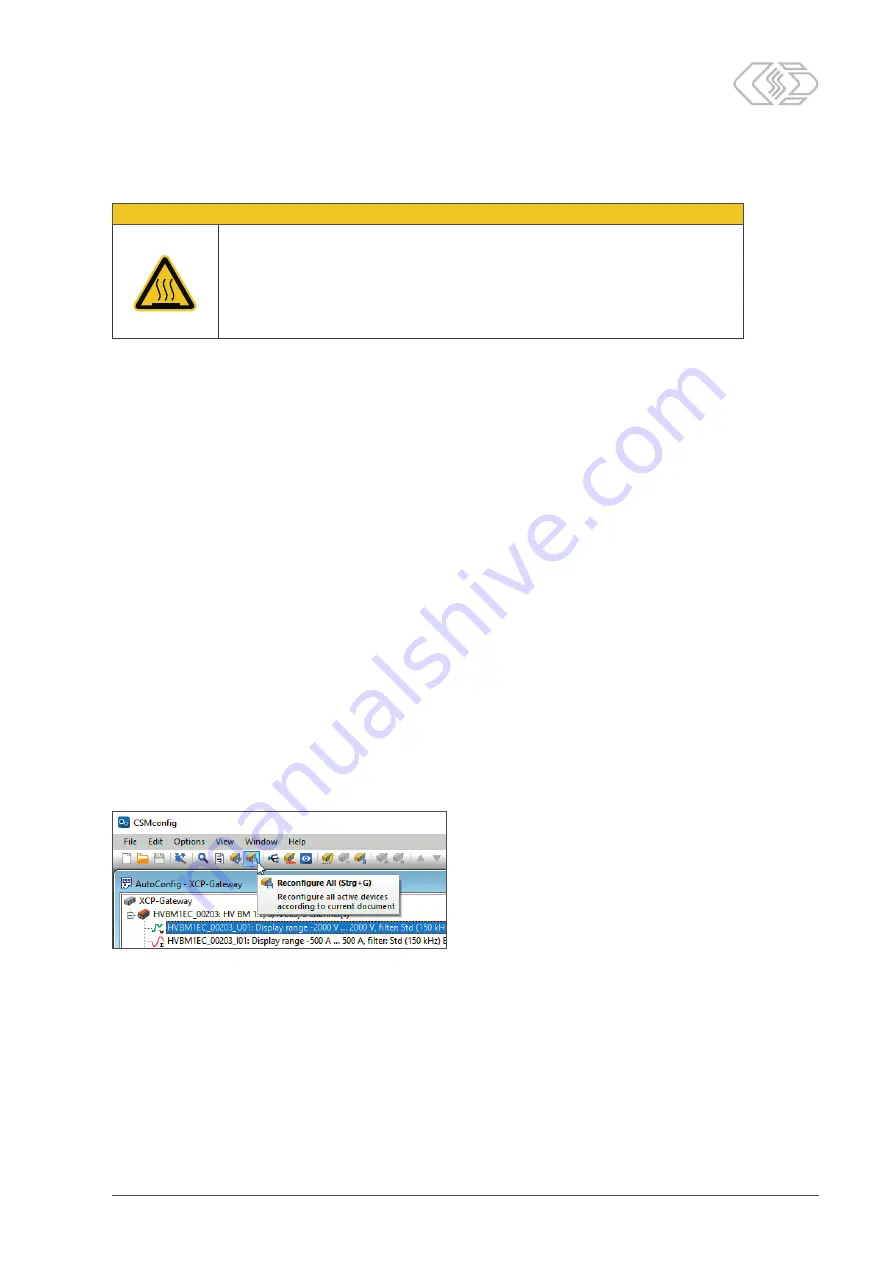
Fig. 5-10:
Reconfigure all
option
"
Select
Reconfigure all
(
→
Ctrl
+
G
).
or
"
Right-click on the device.
"
Select
Write settings to device
(
→
Ctrl
+
W
).


