HV Breakout Module – Appendix
Installation Manual
37
Version 01.20 // 2021
7 Appendix
7.1 Cable preparation
7.1.1 PG gland and spring
NOTE!
Depending on the HV power cables and cable bushings used, there is a risk
of chafing on the pressure screws of the PG glands.
"
Protect the HV power cables by using suitable shrink sleeves if required.
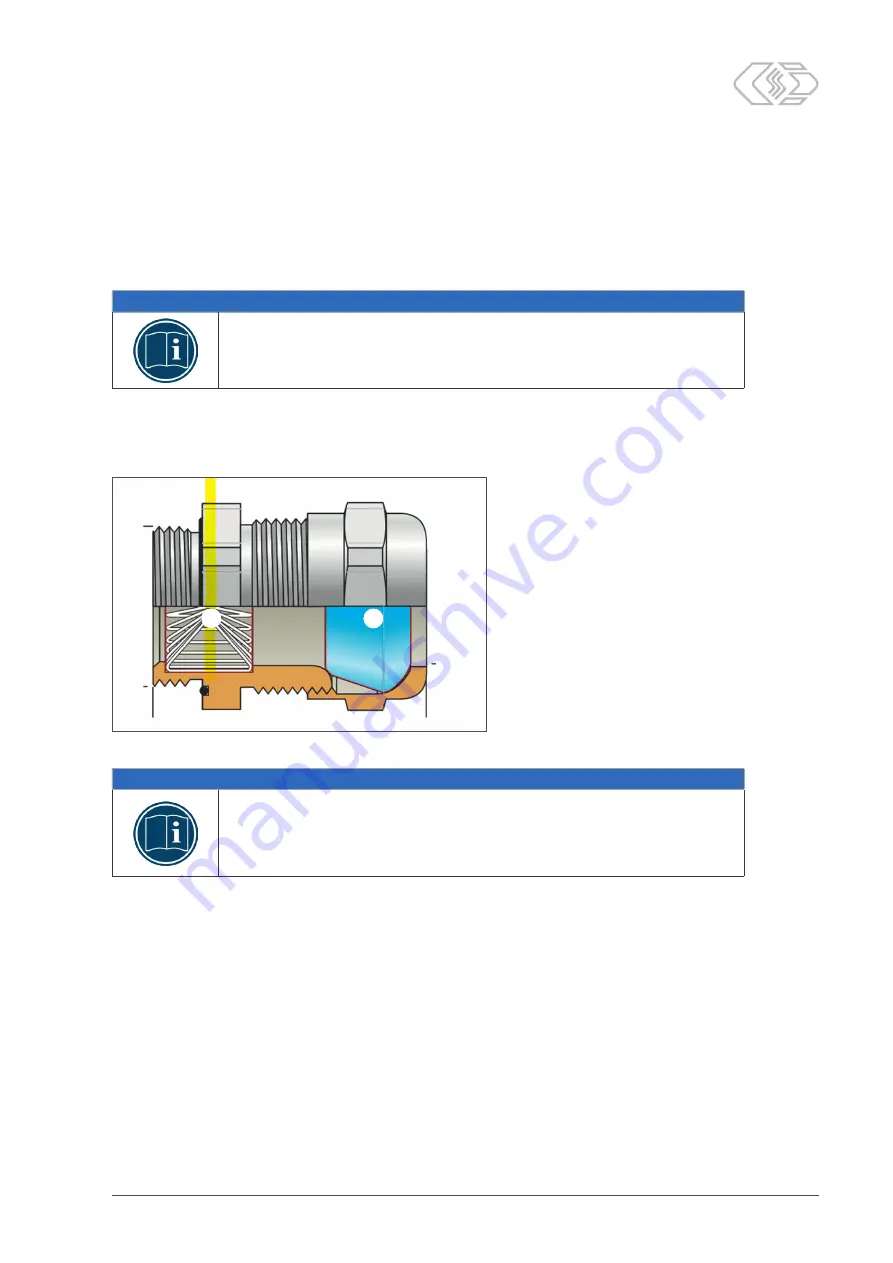
The spring
①
is located exactly on the same level as the sealing insert
②
inside the
connecting thread of the PG gland (Fig. 7-1). To ensure proper contact between the cable
shield and the spring in the PG gland, the cable must be carefully assembled.
Fig. 7-1: PG gland (longitudinal section)
NOTE!
Please note that the installation height of a PG gland changes if a reduction
is used.
If a reduction for an M25 or M20 thread is used with an M32 PG gland, the
total height of the gland increases by approx. 4 mm (Fig. 7-2).
If a reduction is used when mounting an HV power cable, the installation height of the
PG gland changes accordingly. This will also affect the distance between the ring terminal
and the segment of the HV power cable that must be stripped to establish contact between
the spring and the cable shield (Fig. 7-3).
②
①


