


16
Slide cable grip nut (2b), cable grip (2c), bushing (2d) and
cable gland (2e) with o-rings (25) onto cable (2a), and expose
approximately 3” of wire at the end of the cable. Attach ground
screw (33) and washer (39) with ground wire (Green) to the
inside of terminal cavity in discharge case (22). Make wire
connections in accordance to Figure 11 using connectors (29)
and then tape each connector individually with electrical tape.
Fold and insert the connectors and wires into the terminal box
cavity. Insert cap screws (28) with washers (30) and tighten to
15 Ft. Lbs.
Move Bushing (2d), cable grip (2c) and gland nut (2b) into place
and tighten to 25 ft. lbs. Insert cap screws (60) and washers
(61) into clamp (2f), and tighten to 7 ft. lbs. After assembly, an
insulation test (or MEGGER) should be performed per section
F-1.1.
F-6) Motor and Bearing Service:
F-6.1) Disassembly:
To service or replace motor and/or bearings, first remove
discharge case (22) per Section F-5.1 and lower pump end
per Section F-4.1. Remove rotor from stator, remove cap
screws (59) with washers (71) from bearing retainer (57) and
remove bearing retainer (57). Remove bearings (7), (46),
and loading spring (8) from rotor shaft. Use a bearing puller
if needed. Bearings that feel rough, show wear or rust should
be replaced. If stator needs replaced, replace stator and frame
assembly.
F-6.2) Reassembly:
Set the stator/frame assembly and the discharge case in a
vertical position with the discharge case down. Slip the outer
case (21) over the frame (5). Press bearing (7) onto discharge
end of rotor shaft and press bearing (46) with bearing retainer
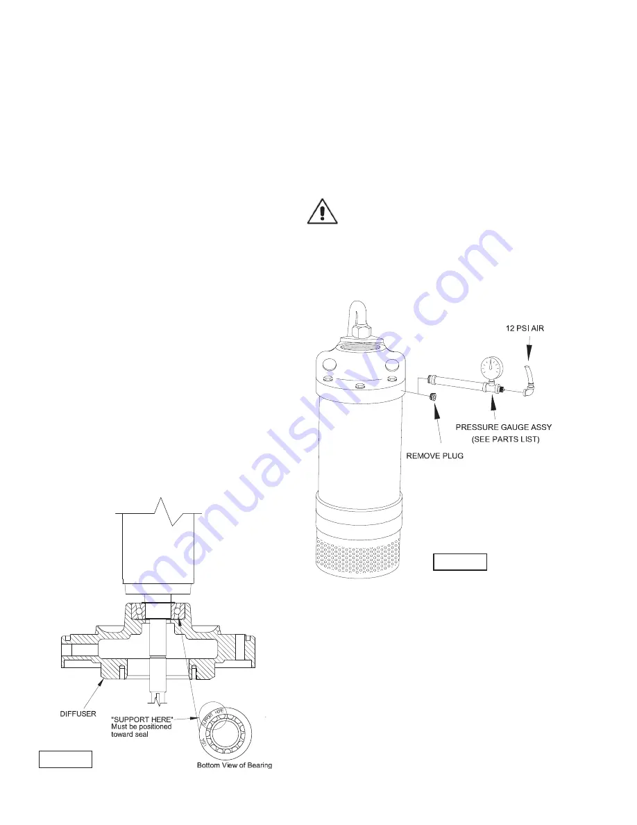
(57) onto suction end of rotor shaft. It is
IMPORTANT
that this
bearing be installed as shown in Figure 12. The outer race
of bearing (46) that is imprinted with the words
“SUPPORT
HERE”
must be positioned toward the diffuser (9). Axial thrust
after start up is in the direction towards the impeller. Inner race
of bearing has more surface area on top side when installed
correctly. When installed correctly, there will be movement
upward in rotor/shaft assembly.
This is opposite of downward thrust which occurs when pump
is running.
“LOOSENESS”
between inner and outer race is
normal for angular contact bearing. Bearing failure will result
in a short period of time if it is not installed as specified. Now
assemble rotor assembly into stator/frame assembly. Assemble
discharge case onto motor/frame assembly per Section F-5.2
and Pump lower end per Section F-4.2. An electrical inspection
should be performed after reassembly per Section F-1.
F-7 Motor Chamber Pressure Test:
After final assembly, pressure test the motor chamber by
removing plug (18) from discharge case (22) and connect an air
hose fitting into the pipe thread. Submerge the pump completely
and apply 12 PSI air pressure.
WARNING! - DO NOT exceed 12 PSI air pressure.
Pump must not show any leakage, if leakage occurs, determine
location and replace defective or damaged parts, then retest
pump.After pump has been tested and no leaks have been
found, remove air hose connection and replace plug (18) using
a sealent, into discharge case (22).
FIGURE 13
FIGURE 12
Summary of Contents for PROSSER STANDARD-LINE 9-81000 Series
Page 5: ...5 inches mm MODEL A B 9 81000 27 38 696 24 00 610 9 81500 29 12 740 25 75 654 A B ...
Page 6: ...6 inches mm MODEL A B 9 82500 33 95 862 30 69 780 9 85000 36 68 932 33 69 856 A B ...
Page 14: ...14 FIGURE 9 ...
Page 19: ...19 FIGURE 14 PUMP SERIES 9 81000 9 81500 ...
Page 20: ...20 FIGURE 15 PUMP SERIES 9 81000 9 81500 ...
Page 23: ...23 FIGURE 16 PUMP SERIES 9 82500 9 85000 ...


