


15
IMPORTANT! - It is extremely important to keep seal
faces clean during assembly. Dirt particles lodged
between these faces will cause the seal to leak.
Place spring (10b) over shaft and in place on rotating member
(10c), making sure it is seated on retainer and not cocked or
resting on bellows tail. Slide retaining ring (10a) over shaft and
let rest on spring (10b). Replace snap ring (11) onto shaft. (See
Figure 9C).
Outer Seal
- Lightly oil
(DO NOT use grease)
outer surface
of stationary member (48d). Press stationary member (48d)
firmly into seal retainer (12), using a seal pusher (see Parts
List - seal tool kit). Nothing but the seal pusher is to come in
contact with the seal face. Make sure the stationary member is
in straight, See Figure 9D. Lubricant O-ring (13) with a grease,
and place it in the groove on seal retainer (12). Place seal
retainer (12) into diffuser (9) and insert screws (14) and tighten,
See Figure 9E.
NOTE:
When installing the seal retainer over
shaft, do not scratch the shaft or seal seat face. Slide a bullet
(see parts list-seal tool kit) over motor shaft.
Lightly oil
(DO NOT use grease)
shaft, bullet and inner surface
of bellows on rotating member (48c). With lapped surface of
rotating member (48c) facing inward toward stationary member
(48d), slide rotating member (48c) over bullet and onto shaft,
using seal pusher, until lapped faces of (48d) and (48c) are
together (see Figure 9F). Place spring (48b) over shaft and
in place on rotating member (48c), making sure it is seated
on retainer and not cocked or resting on bellows tail. Slide
retaining ring (48a) over shaft and let rest on spring (48b), See
Figure 9G. Assemble impeller, suction case and screen per
Section F-3.2. Replace oil as outlined in paragraph F-2.2.
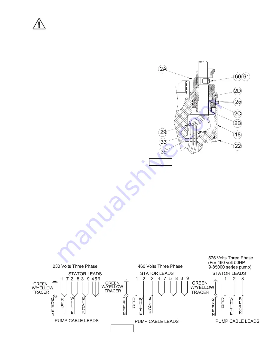
F-5) Discharge & Cable Service:
F-5.1) Disassembly:
Refer to Section F-1 before disassembly. While disassembling,
check for indications of water leaks. Remove cap screws (28)
and washers (30), cable gland assembly (2) and o-rings (25)
from discharge head (22). Use care to avoid damaging the
metal surface. Remove cap screws (60) and washers (61) from
cable clamp (2f). Disconnect cable wires from stator leads by
removing connectors (29), being sure that the stator’s wires
are identified before disconnecting. Check wires for breaks or
cuts. If water is present, there may be leakage through the
cable gland (2e), o-rings (19), (20), (25) and (63), the power
cable (2a) if it has been cut, or the shaft seals (10) and (48).
Check all items and replace if needed. Remove ground screw
(33) and washer (39) from discharge head (22).
Remove cap screws (31), washers (30, on 10-15HP) or (49, on
25-50HP), from discharge head (22). Carefully, using a plastic
hammer, tap the discharge case (22) free from the frame
assembly and remove while feeding the stator wires through
the terminal cavity and stator dam (47) in the discharge case.
Now remove o-rings (19) and (20), replace o-rings showing
any nicks, cuts, cracks, or deformation. To remove cable (2a),
loosen cable grip nut (2b), cable grip (2c) and bushing (2d) and
remove from cable. (See Figure 10).
F-5.2) Reassembly:
To assemble discharge case (22) to stator/frame assembly,
set the assembly in the upright position. Make sure all stator
leads are properly identified (See Figure 11). Each lead should
be color coded or numbered for identification. Apply grease to
o-rings (19) and (20) and place on discharge case (22). Set
the discharge case (22) onto the stator/frame assembly with
the terminal cavity directly over the stator leads and insert the
leads through the stator dam (47) into cavity opening, being
careful not to lose the lead identification numbers or damage
the o-rings. Be sure that load spring (8) is sitting properly in
bearing bore of discharge case. Line up the holes and insert
cap screws (31) washers (30), into holes and torque to 15 Ft.
Lbs. (on 10-15HP) or 26 Ft. Lbs. (on 25-50HP).
FIGURE 10
FIGURE 11
Summary of Contents for PROSSER STANDARD-LINE 9-81000 Series
Page 5: ...5 inches mm MODEL A B 9 81000 27 38 696 24 00 610 9 81500 29 12 740 25 75 654 A B ...
Page 6: ...6 inches mm MODEL A B 9 82500 33 95 862 30 69 780 9 85000 36 68 932 33 69 856 A B ...
Page 14: ...14 FIGURE 9 ...
Page 19: ...19 FIGURE 14 PUMP SERIES 9 81000 9 81500 ...
Page 20: ...20 FIGURE 15 PUMP SERIES 9 81000 9 81500 ...
Page 23: ...23 FIGURE 16 PUMP SERIES 9 82500 9 85000 ...


