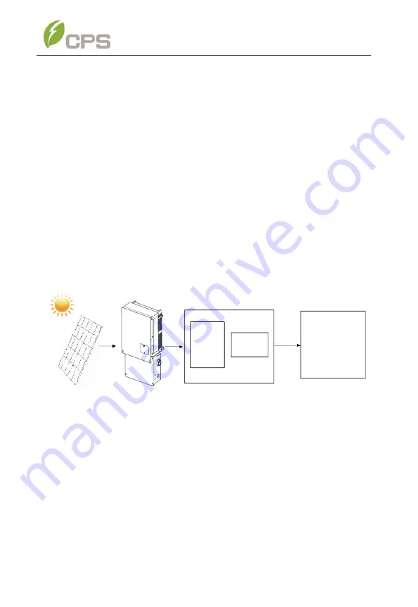
background image


Overview 

2.1 

Inverter for grid-tied PV systems 

CPS  SCA  25  KTL-DO/US-208

CPS  SCA50KTL-DO/US-480  and  SCA60 

KTL- DO/US-480 3-Phase Transformerless String Inverters are designed for 

use  with  an  UNGROUNDED  PV  array  in  carport,  commercial  rooftop,  and 

large utility scale PV grid-tied systems. The system is generally made up of 

PV  modules,  a  3-Phase  String  Inverter  with  a  fused  combiner/disconnect, 

and AC power distribution equipment (Figure 2-1). The inverter converts the 

available DC energy from the PV modules to AC power by synchronizing the 

output current to the same frequency and phase as the AC grid. All or part of 

the AC power is supplied to local loads, and the surplus power is exported to 

the electric utility grid.   

AC Grid


Bidirectional 

electric meter

AC power

 distribution

equipment


Figure 2-1: Grid-tied PV System 


2.2  Product Features 


High  Conversion  Efficiency:

  Advanced  3-level  conversion  topology 

with Space-Vector PWM; SCA25KTL-DO/US-208 Max. efficiency: 97%, 

CEC  efficiency:  96.5%.  SCA50/60KTL-DO/US-480  Max.  efficiency: 

98.8%, CEC efficiency: 98.5%.


Summary of Contents for SCA Series

Page 1: ...CPS SCA Series Grid tied PV Inverter CPS SCA25KTL DO US 208 CPS SCA50KTL DO US 480 And SCA60KTL DO US 480 Installation and Operation Manual Rev3 4 CHINT POWER SYSTEMS AMERICA CO Revision 3 4 May 2020 ...

Page 2: ......

Page 3: ...d kVA Ratings 3 1 3 5 3 3 9 3 Mar 2019 Allow MPPT to be Unbalanced Increased RS485 3pin Terminal LCD interface Parameters Y Comb Terminal 3 2 2 3 Oct 2019 Added Rapid Shutdown Wirebox Removed H4 Wirebox Added water tight design installation requirements 3 3 1 3 3 2 2 3 2 4 3 3 3 Mar 2020 Add disclaimer 1 Update packing list 2 Wiring box bottom seal has been cancelled Installation method pictures A...

Page 4: ...l description Delete wiring box bottom seal description Modify the communication board description Add ISO NE regulation Update partial settings Update datasheet Update 10 3 3 chapter curve and description 3 4 August 2020 Add CPS SCA25KTL DO US 208 model description ...

Page 5: ...7 ANTI ISLANDING DETECTION 15 2 8 DC GROUND FAULT PROTECTION 15 2 9 SURGE SUPPRESSION 15 2 10 DC ARC FAULT PROTECTION 16 2 11 MODULE LEVEL RAPID SHUTDOWN 16 3 INSTALLATION 17 3 1 RECOMMENDATIONS BEFORE INSTALLATION 19 3 2 MECHANICAL INSTALLATION 22 3 2 1 Dimensions 22 3 2 2 Installation Method see Figure 3 2 22 3 2 3 Installation Space Requirement 24 3 2 4 Mounting the Inverter onto the Bracket 28...

Page 6: ... OPERATION STATE 65 4 3 INTERFACE TYPES 66 5 COMMISSIONING 68 5 1 MECHANICAL INSTALLATION CHECK 68 5 2 CONDUCTOR CONNECTIONS CHECK 68 5 3 ELECTRICAL CHECK 68 5 4 COMMISSIONING STEPS 69 6 MAIN MENU AND OPERATION 75 6 1 MEASUREMENT DATA 75 6 2 SETTING 76 6 2 1 System Parameters 78 6 2 2 Control Command 80 6 2 3 Protect Parameters 84 6 2 4 LVRT HVRT Parameters 92 6 2 5 Power Derating Setup 99 6 2 6 R...

Page 7: ...G 127 7 2 LCD FAULT AND TROUBLESHOOTING 128 8 MAINTENANCE AND DE INSTALLATION 134 8 1 PRODUCT MAINTENANCE 134 8 1 1 Check Electrical Connections 134 8 1 2 Clean the Air Vent Grate 134 8 1 3 Replace the Cooling Fans 134 8 1 4 Replace the Inverter 137 8 2 DE INSTALLING THE INVERTER 139 9 ACCESSORIES 141 9 1 FUSE BYPASS TERMINALS 141 9 1 1 Bypass Input Terminal Instructions 141 9 2 SHADE COVER SSC 60...

Page 8: ...45 10 2 MEASUREMENT TOLERANCES 148 10 3 PRODUCTION GRAPHS 149 10 3 1 High Temperature Derating Graph 149 10 3 2 Altitude Derating Graph 150 10 3 3 Grid Voltage Derating Graph 151 10 3 4 Reactive Power Capability 153 11 LIMITED WARRANTY 154 ...

Page 9: ... inverters Audience The information in Chapters 1 Overview 4 User Interface 6 Main Menu and Operation 7 Faut Shutdown and troubleshooting and 9 Accessories is intended for the owner and operator of the inverter and does not require any special training or qualifications The information in Chapters 0 Installation 5 Commisionning 8 Maintenance and De installation is intended for qualified personnel ...

Page 10: ...ion difficulties Installation commissioning troubleshooting and maintenance of the inverter must be performed by qualified personnel If you encounter any problems during installation or operation of this unit first check the user manual before contacting CPS Customer Service This user manual is applicable for the following models CPS SCA 25 KTL DO US 208 CPS SCA50KTL DO US 480 and CPS SCA60KTL DO ...

Page 11: ...arnings and symbols in this document DANGER DANGER indicates a hazardous situation which if not avoided will result in death or serious injury WARNING WARNING indicates a hazardous situation which if not avoided could result in death or serious injury CAUTION CAUTION indicates a hazardous situation which if not avoided could result in minor or moderate injury NOTICE NOTICE indicates a hazardous si...

Page 12: ...taic system are ungrounded and may be energized CAUTION Risk of Electric Shock a Both ac and dc voltage sources are terminated inside this equipment Each circuit must be individually disconnected before servicing b When the photovoltaic array is exposed to light it supplies a dc voltage to this equipment WARNING Electric Shock Hazard The DC conductors of this photovoltaic system are normally ungro...

Page 13: ...NING HAZARDOUS VOLTAGE AREA UNDER THE PLASTIC COVER DO NOT OPEN FUSE HOLDERS UNDER LOAD PERSONAL PROTECTIVE EQUIPMENT MUST BE USED WORN BEFORE ACCESSING FUSES DO NOT OPEN FUSE HOLDERS IF BYPASS TERMINALS ARE INSTALLED WARNING High touch current Earth connection essential before connecting supply INFORMATION For more details please see the user manual ...

Page 14: ...both AC and DC sources Disconnect all energy sources before servicing For continued protection against risk of fire replace only with same type and ratings of fuse DANGER Disconnect the inverter from the AC grid and PV modules before removing covers or opening the equipment Wait at least 5 minutes after disconnecting from the DC and AC sources before servicing or maintaining the inverter Ensure ha...

Page 15: ...m of two is recommended to lift and place the inverter and wirebox into position INSTRUCTION Please check with your local electric utility supply company before selecting a grid standard If the inverter is operated with an incorrect grid standard the electric utility supply company may cancel the interconnection agreement Placing the inverter into operation before the overall system complies with ...

Page 16: ...uipment Figure 2 1 The inverter converts the available DC energy from the PV modules to AC power by synchronizing the output current to the same frequency and phase as the AC grid All or part of the AC power is supplied to local loads and the surplus power is exported to the electric utility grid AC Grid Bidirectional electric meter AC power distribution equipment Figure 2 1 Grid tied PV System 2 ...

Page 17: ...ltage 1000VDC Long Service Life Designed with thin film capacitors to extend inverter s service life 3 MPPTs Multi channel MPPT Maximum Power Point Tracker enables maximum design flexibility and energy harvest optimization over the life of the system Separable Wirebox The wirebox enables fused input of either discrete wiring using the Standard wirebox SCA50 60KTL DO US 480 optional rapid shutdown ...

Page 18: ...tion DC input insulation to ground monitoring DC injection of AC output DC Arc fault detection and circuit interruption Leakage current to ground monitoring Internal enclosure temperature monitoring IGBT power module temperature monitoring KVA overhead to produce rated Active Power at 0 91 power factor Load rejection over voltage LROV protection No neutral connection required delta connection perm...

Page 19: ...att activated Volt Watt activated Set Active Power Function Mode Optional activated under mutual agreement Dynamic Reactive Power Support Mode Optional activated under mutual agreement 2 5 Appearance and Main Item Description 2 8 5 6 7 1 3 4 9 Figure 2 2 Diagram of the Inverter Assembley ...

Page 20: ...n in Figure 2 Figure 2 and Figure 2 The input from PV source circuits passes through surge protection circuitry DC EMI wave filters and independent DC DC boost circuitry to achieve maximum power point tracking and boost the voltages to a common DC bus The inverter uses line voltage and frequency measurements to synchronize to the grid and converts the available PV energy to AC power by injecting b...

Page 21: ...gnal to APS Tigo TS4 A F and TS4 A 2F devices at the array When the inverter senses the loss of AC voltage by way of opening the PV system disconnect switch inverter circuit breaker or under loss of grid events the transmitter ceases the signal sending the MLPE devices into rapid shutdown This rapid shutdown system has been tested and certified with the Tigo TS4 A F and TS4 A 2F platform to confor...

Page 22: ...ER HEAD L1 L2 L3 N PV1 PV1 PV1 PV1 MPPT1 MPPT2 AC Output PV Input PV2 PV2 PV2 PV2 AC Switch Fuses MPPT3 PV3 PV3 PV3 PV3 DC SPD PV1 DC Switch Three level inverter AFD PV2 PV3 PV PE Type Ⅲ MOV Transmitter Vin GND AC DC Power Supply Figure 2 5 CPS SCA25KTL DO US 208 Inverter Schematic Rapid Shutdown RSD Wirebox ...

Page 23: ...ency of the system voltage to deviate significantly which will trigger the inverter to cease operation and disconnect from the grid 2 8 DC Ground Fault Protection The inverters include residual current detection GFCI as part of the DC ground fault detection method required by UL 1741 If there is a ground fault in the PV array the ground fault detection circuitry will detect leakage current trigger...

Page 24: ...inverter is connected to the AC grid the PLC transformer receives power via an integrated power supply Once the transmitter is powered it will send a keep alive signal to the APS TS4 A F 2F mounted integrated at the array Once the inverter senses the grid is missing whether by opening the PV system disconnect inverter circuit breaker or by a loss of grid the transmitter will cease sending this sig...

Page 25: ... mounting bracket user manual and accessory kit Before installation please check that the following items are included in the packages Table 3 1 Main Items No Item Q ty Note Box 1 Main enclosure of the PV inverter 1 A 2 Wiring box of the PV inverter Standard wiring box RSD Wiring box 1 There are two types of wiring box Standard wiring box Integrated DC fuses with every string B RSD wiring box With...

Page 26: ... plug 1 For the RS485 communication Input 3 3 pin PCB connector plug 1 For the RS485 communication Output 4 M8 Nut 4 For the AC terminal block 5 M8 Flat washer 4 For the AC terminal block 6 M8 Spring washer 4 For the AC terminal block 7 Phillips screw 1 Spare for wire box cover INSTRUCTION The items above in Table 3 2 Accessory Kit are for the typical installation configuration The accessories pro...

Page 27: ...nt propagation All conduit entries must be sealed to prevent moisture ingress o Sealing conduits at the other end will provide additional protection firestop putty may be used Separate conduits for and DC cables may prevent arc propagation outside of wire box NOTICE The allowable ambient temperature ranges for the SCA25KTL DO US 208 SCA50KTL DO US 480 and SCA 60KTL DO US 480 3 Phase String Inverte...

Page 28: ... granted permission to connect to the grid Installation personnel must be qualified electricians or those who have received professional training Wear and use proper PPE personal protective equipment during installation Sufficient space according to Figure 3 3 and Figure 3 4 must be provided to allow the inverter cooling system to operate effectively Install the inverter away from flammable and or...

Page 29: ...perature swings especially in cold weather moisture inside the inverter power head could condense over the aluminum heatsink area where inverter semiconductors are mounted Water droplets on the heatsink may cause a short circuit to live semiconductor devices When the PV source is applied to the inverter this PV power source could cause the inverter to fail and result in a short circuit across the ...

Page 30: ...the mounting guidelines below a If the location permits install the inverter mounted vertically b If the inverter cannot be mounted vertically it may be tilted backward at any angle from vertical to 15 from horizontal c When tilted backward at 75 from horizontal in an outdoor environment the CPS Shade Cover SSC 60ST accessory is required to be installed See Section 9 2 for more information d Do no...

Page 31: ...23 e Do not mount the inverter upside down 9 0 1 5 9 0 a b Shade cover c d e Figure 3 2 Inverter Mounting Options ...

Page 32: ...ory must be installed on the inverter to avoid direct sunlight NOTICE The spacing between two adjacently mounted inverters must be 19 7in 500mm Spacing should be increased for installation locations with ambient temperature 45 C Ensure that the air space around the inverter is well ventilated The spacing below the inverter is intended to ensure the LCD and Keypad height are well positioned for the...

Page 33: ... may be reduced to 13 8in 350mm provided a baffle is installed Installing an aluminum or galvanized steel baffle Not supplied by CPS with the dimensions detailed above is intended to divert or deflect warm exhaust air from entering the adjacent inverter Elevated ambient air temperature 45 C will cause the inverter to enter a thermal derating mode and reduce its Active power output ...

Page 34: ... Inverter Pillar or Column Mounting Dimensions INSTRUCTION If the inverter is installed on a pillar or column instead of solid wall the space from the bottom of one inverter to the top of the inverter below may be as small as 11 8in 300mm ...

Page 35: ...27 ...

Page 36: ...cket as shown in Figure 3 6 Figure 3 6 Dimensions of the Bracket Anchoring Holes for Mounting a PV Racking Mount Locate holes or anchors at the marked positions Fasten the Mounting Bracket with the M8x25 Assembling Bolts supplied with the Accessory Kit Note if mounting the Bracket to PV Racking the M8 nuts are not provided in the Accessory Kit Tools Required No 13 wrench es ...

Page 37: ...he holes expansion anchors not provided Fasten the Mounting Bracket with the M8x25 Assembling Bolts supplied with the Accessory Kit Figure 3 7 and Figure 3 8 Tools Required Electric drill Ф10mm 0 4in masonry bit No 13 wrench Figure 3 7 Drill holes set Anchors and tighten Assembly Bolts 1 2 3 Figure 3 8 Secure the Mounting Bracket ...

Page 38: ...n 90 degrees b Manual mounting Two people are required to safely lift the inverter by the grab handle positions marked in Figure 3 10 and mount it onto the bracket CAUTION The main enclosure of the CPS SCA25KTL DO US 208 CPS SCA50KTL DO US 480 and SCA60KTL DO US 480 3 Phase String Inverters is approx 56kg 123 5 pounds Ensure the mounting bracket is properly installed and secured before hanging the...

Page 39: ...31 Figure 3 9 Mount the Main Enclosure on the Bracket by Lifting Sling Figure 3 10 Grab Handle Position ...

Page 40: ...e covers shown below do not have waterproof function Figure 3 11 Main Enclosure Cover Plate b Remove screws securing the bulkhead cover at the top of the wirebox COVER IS NOT WATER TIGHT Figure 3 12 Wiring Bulkhead Cover c Save the bulkhead cover and screws and attach the cover to the left side of the wirebox after the wirebox is attached to the ...

Page 41: ...que value of 4 N m 35 4in lbs CAUTION M6X18 screws must be properly fastened to ensure electrical bond Figure 3 13 Installation of the Wiring Box Step 5 Attach the main enclosure and the wiring box to the mounting bracket with the M6x18 screws 6 pcs see Figure 3 14 Tool required No 3 Phillips head screwdriver torque value of 4N m 35 4in lbs WARNING Ensure the M6x18 screws 4pcs installed in Step 4 ...

Page 42: ...acket Step 6 Attach the bulkhead cover shown in Step 7 Figure 3 12 to the left side of the wiring box see Step 8 Figure 3 15 Tool required No 2 Phillips head screwdriver torque value of 1 6N m 14 2in lbs Figure 3 15 Attach the Cover to the left side of the Wiring Box ...

Page 43: ...nt is installed outdoors The inverter may be locked to the bracket Step 10 Figure 3 16 Figure 3 16 Location of the Anti Theft Padlock The anti theft padlock should meet the dimensional requirements shown in Figure 3 17 B C A Figure 3 17 Dimensions of Anti Theft Padlock Shackle Recommended lock size A Shackle diameter 3 6mm B Shackle width 20 50mm C Shackle height 20 50mm ...

Page 44: ...ownloads link to acess the CPS String Sizing tool This is an optional design tool to help guide designers by matching the PV panel type and quantity to the inverter s power rating WARNING Prior to performing any electrical installation ensure the M6x18 screws 4pcs installed in Step 4 of section 3 2 4 Mounting the Inverter onto the Bracket are properly torqued and the area under the bolt head is cl...

Page 45: ...rews on the wiring box and remove the cover See Figure 3 19 Figure 3 19 Removing the Wiring Box Cover To reinstall the cover replace cover and align the screws Use a No 3 Philips head screwdriver to secure the 4 screws on the cover Torque to 35 4 in lbs 4 N m ...

Page 46: ... 32in 8mm 2 87in 73mm 4 29in 109mm Figure 3 20 Conduit Knock out Locations on the wirebox Knock outs for DC input 3 1 1 2 inch Trade Size 1 98 Dia and 1 removable gland plate for custom size conduit i e when use of 2 inch or 2 1 2 inch Trade Size conduit is required later models may not have gland plates Knock outs for communication 3 4 inch Trade Size 1 11 Dia ...

Page 47: ...when use of 2 inch or 2 1 2 inch Trade Size is required External ground connection point M6 6 7 7 8 5 5 Figure 3 21 Internal Connection Points within the Standard wirebox only for CPS SCA50 60KTL DO US 480 6 7 7 8 9 5 10 Figure 3 22 Internal Connection Points within the RSD wirebox only for CPS SCA50 60KTL DO US 480 ...

Page 48: ...h are electrically divided into separate PV input zones PV Input 1 PV Input 2 and PV Input 3 Each 5 string PV input zone operates as a separate and independent Maximum Power Point Tracker MPPT Independent mode can be very useful for sites with partial shading of the array or with arrays consisting of different tilt or azimuth Each MPPT employs a method known as P O perturb and observe for seeking ...

Page 49: ...Start up Voltage Power 330 80W 330 80W 330 80W Operating Voltage 200 950Vdc 200 950Vdc 200 950Vdc MPPT Voltage Range 480 850Vdc 480 850Vdc 540 850Vdc Maximum PV Current Isc x 1 25 45A 68A 68A INSTRUCTION PV input power from the array may be unbalanced between the three MPPT zones however every effort should be made to design within one string count difference See Table 3 3 When designing the PV sy...

Page 50: ...y as an exception Every effort should be made to design within one string count difference for each of the three MPPTs to avoid unnecessary power clipping When the input power for one MPPT zone exceeds the individual maximum allowed Max PV Power however the combined input power is below the inverter maximum input specifications the inverter may be set to operate in Parallel Mode 1 MPPT In this mod...

Page 51: ...t grounding conductor to ensure operational safety The grounding busbars are electrically bonded by way of the inverter chassis 3 3 3 2 DC Fuse Configuration Selection The CPS SCA25KTL DO US 208 CPS SCA50KTL DO US 480 and SCA60KTL DO US 480 inverter wire boxes include touch safe fuse holders and preinstalled 20A DC fuses as factory standard Ensure that the appropriate fuse values are used dependin...

Page 52: ...d wiring to reduce PV source circuit home runs CPS allows replacement of the factory installed 15A fuses with appropriate ampere ratings however CPS does not provide nor stock these fuses NOTICE When installing replacement 25A or 30A fuses these fuses may not be installed in adjacent fuse holders An empty or unused fuse holder must be positioned between each 25A 30A fuse within each MPPT When Y br...

Page 53: ...performance of the inverter please read the following guidelines before performing any DC connections 1 Confirm the maximum open circuit voltage of the PV modules is lower than 1000VDC under any conditions 2 Confirm that the PV modules for each MPPT within the inverter are of the same type and specification before connection 3 Ensure correct polarity of the PV Strings before terminating the DC sou...

Page 54: ...ied by either Sinofuse or Mersen Ferraz Shamut The touch safe fuse holders have unique terminal torque values specified by their manufacturers See Table 3 7 for specified torque values NOTICE It is important to use a multi meter to check the polarity of the DC source circuit conductors to avoid any risk of reverse polarity WARNING A reversed string is not protected by the inverter and can cause se...

Page 55: ... the factory installed liquid tight hole plugs from the DC knockout holes in the wiring box and install 1 1 2 inch Trade Size conduit and conduit fittings If the use of smaller conduit is desired proper weather tight reducing bushings may be installed Confirm all fittings are NEMA 4X rated properly tightened and route the DC source circuit conductors through the conduit into the wiring box 2 Refer...

Page 56: ... of the string conductor Insert the conductor into the fuseholder terminal ensuring the stranding of the conductor remains firmly twisted and does not separate Tighten the screw clamp to the torque specified in Table 3 7 Continue terminating the remaining strings in this manner for each MPPT PVIn1 PVIn2 PVIn3 4 Terminate at busbar RSD wirebox The RSD wirebox only contains fuseholders for the posit...

Page 57: ...al PV string fused combiners are used The Bypass Terminals allow for larger single conductors to be terminated at each MPPT within the wirebox bypassing the input fuses as shown in Figure 3 26 See Section 9 Accessories for installation information Figure 3 26 Bypass Terminal option installed within the Standard wirebox Only for CPS SCA50 60KTL DO US 480 Before terminating the PV conductors verify ...

Page 58: ...d connections 3 3 4 1 Acceptable Transformer Configurations The SCA25KTL DO US 208 inverters operate at 208VAC Wye output SCA50 60KTL DO US 480 inverters operate at 480VAC Wye output If another voltage configuration is required a transformer may be necessary Wye Inverter DELTA Utility Wye Inverter WYE Utility TRANSFORMER INVERTER L1 L2 L3 N PE A C B PE N UTILITY PER CODE OPTIONAL PER CPS TRANSFORM...

Page 59: ...ted to ground additional ground fault detection must be added external to the inverter per NEC 250 21 In a Delta connected system the inverter does not detect AC Side Ground Faults Only DC Side Ground Fault protection is provided by the inverter Additional AC ground fault detection must be added external to the inverter per NEC 250 21 Figure 3 27 AC Acceptable Transformer Winding Configurations ...

Page 60: ...EE C57 159 2016 Guide on Transformers for application in Distributed Photovoltaic DPV Power Generation Systems It is the responsibility of the system designer to determine and take in account the reliability of the transformer or other system parameters 5 The transformer does not require a static shield 6 The maximum number of inverters connected to a single transformer is 70 7 The recommended max...

Page 61: ...iquid tight hole plug from the right side or bottom of the AC input portion of the wiring box to install 1 1 2 inch Trade Size conduit and conduit fittings into the hole Then route the cables through the conduit inside the wiring box DC INPUT COMM PORT For more details please see the user manual WARNING High touch current Earth connection essential before connecting supply AC OUTPUT Figure 3 28 AC...

Page 62: ...nding via the ground busbar left 1 This is required for grounding the equipment by running the EGC with the ungrounded conductors b Bonding via the external grounding point right 2 The external bonding connection is provided in case the inverter mount needs to be bonded to a metallic structure on which it may be mounted Figure 3 29 AC Output and Ground Cable Connection ...

Page 63: ... CU 5 65 N m 50 in lbs External grounding point 6 4 AWG CU 5 65 N m 50 in lbs The maximum acceptable conductor size that may be terminated to the AC output terminal is restricted based on the compression lug maximum dimensions shown in Figure 3 15 16 max 5 16 min 7 16 max 3 4 max 13 16 max 1 2 max 24 5mm max 8mm min 11 5mm max 19mm max 21mm max 12 5mm max Standard 1 hole Lug Metric 1 hole Lug Figu...

Page 64: ...minal block The neutral conductor is optional The inverter may be wired as a 3 wire or 4 wire connection the PE ground is ALWAYS required When terminating the ground at the busbar a ferrule is recommended but not required See the 1 st diagram in Figure 3 Set up the conductors referring to Figure 3 30 Pre insulated end ferrule 1pcs OT type terminal 4pcs Pre insulated end ferrule Core wire OT type t...

Page 65: ...nt event occur The Grid connection type should be a 4 wire Wye grounded neutral the inverter may connect to the grid via 3 or 4 wires The neutral conductor from the inverter to point of interconnection POI is optional A floating delta is allowed but ground fault protection must be provided external to inverter Either 3 pole or 4 pole AC circuit breaker OCPD may be selected as per the following tab...

Page 66: ... US 208 CPS SCA50KTL DO US 480 and SCA60KTL DO US 480 inverters support industry standard Modbus RS485 communication 1 2 3 ON OFF S1 5 OFF ON 12V 12VGND RS485_B RS485_A 485_GND 12V 12VGND RS485_B RS485_A RS485_GND RS485_GND RS485_A RS485_B P9 P6 P7 P8 S1 P1 OFF ON 12V 12VGND RS485_B RS485_A 485_GND 12V 12VGND RS485_B RS485_A RS485_GND RS485_GND RS485_A RS485_B P9 P6 P7 P8 S1 P1 4 Figure 3 32 Commu...

Page 67: ...0Ω terminal resistor switch for communications 1 ON Enable termination resistance 2 OFF Disable termin tion resistance Figure 3 33 Communication Connection Interfaces 3 4 2 RS485 Communication CPS recommends the following cable for inverter RS485 communications UTP CAT 5e or 3 18 22AWG communication cables It is recommended that industrial grade shielded RS485 cable be used in lieu of unshielded t...

Page 68: ..._B P9 P6 P7 P8 S1 P1 12VGND 12V P9 RS485 1 RS485 2 P7 P7 RS485_A RS485_B RS485_GND Figure 3 34 RS485 Connection of Communications Board 3 4 3 RS485 Network Set up When the inverters are monitored via the RS485 communication a unique RS485 address for each inverter can be set up through the LCD interface Up to 32 inverters can be connected in the RS485 communication network The daisy chain topology...

Page 69: ...and AC sources before servicing or maintaining the inverter Ensure hazardous high voltage and energy inside the inverter has been discharged prior to servicing If there are multiple inverters in the RS485 network the selector switch S1 of the last inverter in the daisy chain should be in ON position to have the 120Ω terminal resistor enabled The selector switch S1 of all other inverters should be ...

Page 70: ...ring correct polarity and using a shielded twisted pair cable 4 If the inverter is the last Modbus device in the daisy chain make sure the Modbus termination switch S1 is in the ON position enabling Modbus termination Do not turn the switch to the ON position in any other inverters of the daisy chain If there is only one inverter the Modbus termination switch S1 should be set to ON 5 The shield of...

Page 71: ...gure 4 1 LCD Panel The LCD panel includes a screen saver function to increase the service life of the display If there is no user activity or operation key press for greater than 1 minute the display will enter the screen saving mode to protect the screen and prolong the service life During normal inverter operation a key press or any warnings or system faults that may occur will cause the LCD to ...

Page 72: ...d running status light up 0 5s light off 1 6s Light off In other operation status or power supply not working GRID Grid status indication light Light on Grid is normal Flash Grid fault light up 0 5s light off 1 6s Light off Power supply not working FAULT Fault status indication light Light on Indicates a Fault Slow flash Indicates Alarm light up 0 5s light off 2s Fast flash Protective action light...

Page 73: ... under DSP control when POWER lights up RUN LED will illuminate when the inverter detects that the grid connection conditions meet the requirements and power is being fed into the grid The RUN LED will blink if the grid is in a de rated running state while feeding power into the grid Derate may be caused by low grid voltage mppt voltage out of range or excessive temperature GRID LED will illuminat...

Page 74: ...e Normal operation and Standby modes as shown in Figure 4 3 Default Display Interface for Normal Operation and Fault mode as shown in Figure 4 4 History Record Interface 1 The LCD interface starts with the company logo once the system is energized as shown in Figure 4 2 Chint Power System Initialization Figure 4 2 LOGO Interface 2 While the inverter is in Normal Operation mode and not in screen sa...

Page 75: ... it turns back to normal mode The inverter will switch from standby mode to fault mode if a malfunction occurs E T 0 0kWh 2015 10 22 12 00 00 E D 0 0kWh 3 6 9 12 15 18 21 24h 15 30 45 60 kWh Standby Addr 001 PV1 0 0V 0 0A Figure 4 3 Default Display Interface for Normal Operation 4 If the inverter experiences a Fault it will enter Fault mode and display the current or most recent faults History Rec...

Page 76: ...ll conductors are connected to the right terminals and properly labeled The appropriate cable management is important to avoid physical damage No sharp edges from cable ties exist Check polarity of DC input conductors The DC Switch should be in the OFF position Refer to 3 3 Electrical Installation 5 3 Electrical Check Make sure that the AC circuit breaker is appropriately sized Test whether the AC...

Page 77: ...D screen of inverter will light up The inverter will then start up with the message sys checking When the inverter completes Initialization the LCD will show the screen as Figure 5 1 below Chint Power System Initialization Figure 5 1 System Initialization Logo 4 Setting Language Press ENT to access the main menu select Setting and press ENT The password is 1111 using the arrow keys enter the passw...

Page 78: ... Scroll to Grid Connection Rule and press ENT Use the arrow buttons to move up down to the required grid standard Press ENT to select the required standard INSTRUCTION Check with your local utility company before selecting a grid standard If the inverter is operating with a wrong grid standard the utility company may cancel the interconnection agreement Placing the inverter into operation before t...

Page 79: ...Parameters menu Select Time and press ENT Scroll up down to select the numerical value then press ENT to go to next option e g Year to Month press ESC to go to last option e g Month to Year Finally Press the ENT key to confirm the setting Press more than 1 second to go to last position of the number when setting the parameters e g 2008 to 2008 Press more than 1 second to go to the next position of...

Page 80: ...tting 8 Neutral Line Setting From the previous menu press ESC to return to the System Parameters menu Select Neutral Line Setting and press ENT Use the arrow keys to highlight Yes or No in regard to whether a neutral conductor is present Press ENT This setting will allow the inverter to display L N voltages on the LCD It will not affect the operation of the inverter Neutral Line Setting No Yes Fig...

Page 81: ...must have a unique address Scroll up down to choose an address for the inverter and press ENT Addresses can be assigned from 1 128 See Figure 5 7 Communication Setting Baud rate 9600 Address 0001 Figure 5 7 Communication Setting 10 Setting the LCD contrast grade From the previous menu press ESC to return to System Paramters menu Select LCD Contrast Setting and press ENT Using the up down arrows in...

Page 82: ...e and the fault menu will be displayed Select Current Error and press ENT to access the current faults the inverter has recorded This information will show on the LCD screen as shown in the Figure 5 9 Current Error P1 1 Date Fault 2015 10 22 12 20 08 ArcboardErr 2015 10 22 12 20 08 2015 10 22 12 20 08 Fault0040 2015 10 22 12 20 08 2015 10 22 12 20 08 Time Fault0040 Fault0040 Fault0040 Figure 5 9 F...

Page 83: ...Menu on the LCD Screen The main menu of the LCD screen has 5 menus Measurement Data Setting Power ON OFF History Record and Device Information The users may select options by moving the curser up down with and and then press the ENT key to confirm the selection The users can return to the default indication interface by pressing the ESC key 6 1 Measurement Data When Measurement Data is selected in...

Page 84: ... 100 0 1 000 0 0 Grid Connection Rule IEEE1547 Power Derating Main Menu Measurement Data History Record Power On Off Device Information Setting 0 0 E Total kWh Thdv L1 L3 0 0 0 0 0 0 ThdI L1 L3 0 0 0 0 0 0 Figure 6 2 Operation Information 6 2 Setting Move the cursor to Setting in the main interface Press the ENT key to be prompted for the password 1111 as shown in Figure 6 3 Enter the password num...

Page 85: ... contains eight submenus System Parameters Control Command Protection Parameters LVRT HVRT Setup Power Derating Setting Reactive Power Derating Setup ARC Parameters and Other Parameters Setting P2 2 LVRT HVRT Setup Others Parameters Setting P1 2 System Parameters Protection Parameters Power Derating Setup Reactive Power Derating Setup ARC Parameters Control Command Figure 6 4 System Setup Menu and...

Page 86: ...ble in Language menu Language setting ENGLISH 中文 Figure 6 5 Language Setting 2 Grid Connection Rule Multiple grid standards are available Press and to select the corresponding grid standard required for the installation and press the ENT key Grid Connection Rule IEEE1547_2003 CA Rule 21 HECO HM HECO ML IEEE1547_2014 Only for CPS SCA25KTL DO US 208 ...

Page 87: ...hanged 4 Neutral Line Setting This option allows the user to select Yes No if a neutral conductor has been connected to the inverter This setting INSTRUCTION Please check with your local electric utility supply company before selecting a grid standard If the inverter is operated with an incorrect grid standard the electric utility supply company may cancel the interconnection agreement Placing the...

Page 88: ...o go to next option e g Year to Month press ESC to go to last option e g Month to Year Finally Press the ENT key to confirm the setting Press more than 1 second to go to last position of the number when setting the parameters e g 2008 to 2008 Press more than 1 second to go to the next position of the number when setting the parameters e g 2008 to 2008 7 LCD Contrast Setting Press or to increase de...

Page 89: ... inverter is not in operation mode Otherwise Fault Operated will be reported 3 ARC Detect Mannually begin an arc fault test The inverter will cease power production and test ARC Arcing check and protection is mainly divided into two parts the Arcing check board is responsible for whether there is Arcing in line and transfer an Arc protection signal to the DSP in the dominating control INSTRUCTION ...

Page 90: ...ursor to this item and press the ENT key to initiate the scanning The LCD screen will skip to normal operation interface if the MPPT scanning succeeds or remain on the MPPT Scan menu interface if the scanning fails The factory default setting for MPPTScan is set to Enabled yet can also be set to Disabled When the MPPT scan function is enabled the default scan period is every 60 minutes The inverte...

Page 91: ...83 ...

Page 92: ...00 00 90 08 107 92 300 00 59 8 Enable Disable Disable Grid Voltage Balance P7 7 GridVoltUnbalance 10 00 Disable Enable Disable Enable Enable Enable Grid Over Frequency Protection P3 7 FrqMaxTripT1 S GridFrqMax1 Hz GridMaxTripT2 S GridFrqMax2 Hz FrqMaxTripT3 S GridFrqMax3 Hz 0 16 62 2 00 60 5 0 16 Enable Enable Disable Disable Enable Enable 62 LVRT HVRT Setup Setting P1 2 System Parameters Protecti...

Page 93: ...axTripTi me2 S Level 2 Max grid trip voltage 0 0 16 655 0 0 16 655 0 0 16 655 GridVoltMax3 Level 3 Max grid voltage 100 120 135 100 120 135 100 120 00 135 VoltMaxTripTi me3 S Level 3 Max grid trip voltage 0 0 16 655 0 0 16 655 0 0 16 655 GridVoltMin1 Level 1 Min grid voltage 30 88 100 30 88 100 30 88 00 100 VoltMinTripTi me1 S Level 1 Min grid trip voltage 0 2 655 0 20 5 655 0 2 00 655 GridVoltMin...

Page 94: ...x grid trip voltage 0 00 0 16 655 00 0 00 0 16 655 00 GridVoltMax3 Level 3 Max grid voltage 100 00 120 00 135 00 100 00 120 00 135 00 VoltMaxTripTime3 S Level 3 Max grid trip voltage 0 00 0 16 655 00 0 00 0 16 655 00 GridVoltMin1 Level 1 Min grid voltage 30 00 88 00 100 00 30 00 88 00 100 00 VoltMinTripTime1 S Level 1 Min grid trip voltage 0 00 2 00 655 00 0 00 2 00 655 00 GridVoltMin2 Level 2 Min...

Page 95: ...ncy 0 0 16 655 0 0 16 655 0 0 16 655 GridFrqMax3 Protection threshold value of Level 3 Max grid frequency 60 62 65 60 62 65 60 62 0 65 FrqMaxTripT3 S Trip time of Level 3 Max grid frequency 0 0 16 655 0 0 16 655 0 0 16 655 GridFrqMin1 Protection threshold value of Level 1 Min grid frequency 54 59 5 60 54 58 5 60 54 58 5 60 FrqMinTripT1 S Trip time of Level 1 Min grid frequency 0 2 655 0 299 5 655 ...

Page 96: ...16 655 00 GridFrqMax3 Protection threshold value of Level 3 Max grid frequency 60 00 62 00 65 00 60 00 62 00 65 00 FrqMaxTripT3 S Trip time of Level 3 Max grid frequency 0 00 0 16 655 00 0 00 0 16 655 00 GridFrqMin1 Protection threshold value of Level 1 Min grid frequency 48 00 59 50 60 00 48 00 59 50 60 00 FrqMinTripT1 S Trip time of Level 1 Min grid frequency 0 00 2 00 655 00 0 00 2 00 655 00 Gr...

Page 97: ... 300 00 655 FrqMax Hz Recovery Max threshold of grid Frequency protection 54 60 30 66 54 60 4 66 54 61 0 66 FrqMin Hz Recovery Min threshold of grid Frequency protection 54 59 8 60 54 58 6 60 54 58 7 60 FrqRecoveryT S Recovery time of grid frequency protection 0 300 655 0 300 655 0 300 00 655 Grid Voltage Moving Average VoltMax The Max grid voltage of moving average filter 100 110 135 100 110 135 ...

Page 98: ...0 PhaseLoseRcvCoeff PhaseLoseRcvCoeff 0 5 2 0 30 0 0 5 2 0 30 0 0 5 2 0 30 0 PhaseLoseVUnbala nce PhaseLose Voltage Unbalance 0 01 10 00 100 00 0 01 10 00 100 00 0 01 10 00 100 00 Phase PETripVolt The trip voltage of Phase PE 0 01 45 00 100 00 0 01 45 00 100 00 0 01 45 00 100 00 Phase PERcvVolt The recovery voltage of Phase PE 0 01 35 00 100 00 0 01 35 00 100 00 0 01 35 00 100 00 ...

Page 99: ...ncy protection 54 0 60 30 66 00 54 0 60 30 66 0 FrqMin Hz Recovery Min threshold of grid Frequency protection 48 00 59 80 60 00 48 00 59 80 60 00 FrqRecoveryT S Recovery time of grid frequency protection 0 00 300 00 655 00 0 00 300 00 655 00 VoltMax The Max grid voltage of moving average filter 100 00 110 00 135 00 100 00 110 00 135 00 MaxTripT s The trip time of the Max grid voltage of moving ave...

Page 100: ...00 0 00 LVRTVol2 45 00 1 20 P2 7 10 50 65 00 10 50 45 00 65 00 20 50 LVRTTime2 s LVRTTime3 s LVRTVol3 LVRTVol4 LVRTTime4 s LVRTVol5 LVRTTime5 s LVRTTime6 s LVRTVol6 P3 7 20 50 83 00 20 50 83 00 LVRTTime7 s LVRTTime8 s LVRTVol7 LVRTVol8 HVRTTime1 s HVRTVol1 P4 7 0 80 125 00 0 00 125 00 HVRTVol2 124 00 0 80 P5 7 12 50 115 00 12 50 124 00 115 00 12 50 HVRTTime2 s HVRTTime3 s HVRTVol3 HVRTVol4 HVRTTim...

Page 101: ...2 4 6 8 10 12 14 16 18 20 22 1 2 3 4 5 6 7 8 Through Trip Voltage N rated Time S Figure 6 11 The LVRT Curve 1 3 1 25 1 2 1 15 1 1 1 05 1 2 4 6 8 10 12 14 16 18 20 22 1 2 3 4 5 6 7 8 Through Trip Voltage N rated Time S Figure 6 12 The HVRT Curve ...

Page 102: ...th point 0 0 45 45 100 100 0 0 50 50 100 100 0 0 30 45 100 100 LVRTTime 3 4 Time of Level Low voltage ride through 3rd 4th point 0 0 1 20 10 50 655 655 0 0 1 20 10 50 655 655 0 0 0 16 0 21 655 655 LVRTVolt 5 6 Threshold value of Low voltage ride through 5th 6th point 0 0 65 65 100 100 0 0 70 70 100 100 0 0 45 65 100 100 LVRTTime 5 6 Time of Level Low voltage ride through 5th 6th point 0 0 10 50 20...

Page 103: ...00 100 00 0 00 0 00 45 00 45 00 100 00 100 00 LVRTTime 3 4 S Time of Level Low voltage ride through 3rd 4th point 0 00 0 00 1 20 10 50 655 00 655 00 0 00 0 00 1 20 10 50 655 00 655 00 LVRTVolt 5 6 Threshold value of Low voltage ride through 5th 6th point 0 00 0 00 65 00 65 00 100 00 100 00 0 00 0 00 65 00 65 00 100 00 100 00 LVRTTime 5 6 S Time of Level Low voltage ride through 5th 6th point 0 00 ...

Page 104: ...24 124 135 135 100 100 120 120 135 135 100 100 120 117 5 135 135 HVRTTime 3 4 Time of Level high voltage ride through 3rd 4th point 0 0 0 80 12 50 655 655 0 0 0 11 12 50 655 655 0 0 0 25 0 25 655 655 HVRTVolt 5 6 Threshold value of high voltage ride through 5th 6th point 100 100 115 115 135 135 0 0 110 110 135 135 0 0 117 5 115 0 135 135 HVRTTime 5 6 Time of Level high voltage ride through 5th 6th...

Page 105: ...5 00 100 00 100 00 124 00 124 00 135 00 135 00 HVRTTime 3 4 S Time of Level high voltage ride through 3rd 4th point 0 00 0 00 0 80 12 50 655 00 655 00 0 00 0 00 0 80 12 50 655 00 655 00 HVRTVolt 5 6 Threshold value of high voltage ride through 5th 6th point 100 00 100 00 115 00 115 00 135 00 135 00 100 00 100 00 115 00 115 00 135 00 135 00 HVRTTime 5 6 S Time of Level high voltage ride through 5th...

Page 106: ... Enable reactive power output 0 0 2 0 2 2 0 2 2 LVRTTripVolt Threshold value of LOW voltage trip 70 80 100 70 88 100 70 88 100 LVRTPstReacti ve1 The factor LVRT Positive Reactive Current 0 150 300 0 150 300 0 150 300 LVRTNegReact ive1 The factor LVRT Negative Reactive Current 0 200 300 0 200 300 0 200 300 HVRTModeSet ting 0 Disable 1 Enable no reactive power output 2 Enable reactive power output 0...

Page 107: ...factor LVRT Positive Reactive Current 0 0 150 0 300 0 0 0 150 0 300 0 LVRTNegReact ive1 The factor LVRT Negative Reactive Current 0 0 200 0 300 0 0 0 200 0 300 0 HVRTModeSet ting 0 Disable 1 Enable no reactive power output 2 Enable reactive power output 0 0 2 0 0 2 HVRTTripVolt Threshold value of HIGH voltage trip 100 0 110 0 135 0 100 0 110 0 135 0 6 2 5 Power Derating Setup Power Derating Setup ...

Page 108: ... Hz 60 OvrFrqDeratingMode 0 Power vs Grid Frequency LVRT HVRT Setup Setting P1 2 System Parameters Protection Parameters Power Derating Setup Reactive Power Derating Setup ARC Parameters Control Command Power vs Grid Voltage P1 3 Disable VwCurveV2 106 00 VwCurveV1 VwCurveP1 VwCurveP2 OPenLoopRespT s 100 00 110 00 0 0 10 0 Figure 6 13 Power Derating Setup ...

Page 109: ...rvoltage derating end voltage V2 106 110 110 106 110 110 106 110 110 VwcurveP2 Grid overvoltage derating end power P2 0 0 100 0 0 100 0 0 100 OpenloopRespT Open loop response time 0 5 10 90 0 5 10 90 0 5 10 90 Grid Over Frequency Derating OvrFrqMin Hz The trigger frequency of Over Frequency derating 54 60 50 72 54 60 10 66 54 60 5 66 OvrFrqMax Hz The end frequency of Over Frequency derating 60 61 ...

Page 110: ... 100 0 100 100 0 100 100 Table 6 14 Power Derating Setup Only for CPS SCA25KTL DO US 208 Grid Over Frequency Derating Setting Range Parameter Name LCD Display Description IEEE1547 Rule21 Min Default Max Min Default Max VwcurveV1 Grid overvoltage derating starting voltage V1 105 00 106 00 109 00 105 00 106 00 109 00 VwcurveP1 Grid overvoltage derating starting power P1 0 0 100 0 100 0 0 0 100 0 100...

Page 111: ...g 58 80 60 00 66 00 58 80 60 00 66 00 OvrFrqRecoveryT s The recovery time of OverFrequency derating 0 60 1200 0 60 1200 OvrFrqDeratingM ode Over frequency derating enable disable 0 Disable 1 Enable 0 0 1 0 0 1 CtrMode The control mode of active power 0 Disable dispatch 1 Remote dispatch 2 Local control 0 0 2 0 0 2 Percentage Local electric dispatch Active Power setting value 0 0 100 0 100 0 0 100 ...

Page 112: ... Control Command PFSetValue 1 000 Reserve Only for CPS SCA25KTL DO US 208 PF vs Grid Voltage PFCurveP1 P1 4 PFpCurvePF1 100 0 1 000 50 0 PFpCurvePF2 PFCurveP2 PFCurveTriVolt PFCurveUndoVolt 0 900 100 00 90 00 QuCurveQ2i P3 4 5 0 20 0 50 0 QuCurveTriPower QuCurveUndoPower Reactive Power vs Grid Voltage Grid Reactive Power Derating P4 4 CtrMode 0 Percentage 0 0 Reactive Power vs Grid Voltage QuCurve...

Page 113: ...rvePF2 PF of PF P Curve point 2 1 0 0 8 0 9 0 8 1 0 1 0 0 8 0 9 0 8 1 0 1 0 0 8 0 9 0 8 1 0 PFCurveTriVolt V The trigger voltage of PF P Curve 100 100 110 100 100 110 100 100 110 PFCurveUndoV olt V PF curve revocation voltage 90 90 100 90 90 100 90 90 100 Table 6 16 Reactive Power Control IEEE 1547 and Rule21 Only for CPS SCA25KTL DO US 208 Grid Reactive Power Derating Setting Range Parameter Name...

Page 114: ...he PF and Q value can be adjusted by remote software if the Remote setting is selected 1 PFSetValue Set the PF value This function changes the reactive power by adjusting the Power Factor 2 PFpCurve functions PFp curve mode Using the curves to set the PFp setpoints See Figure 6 15 These functions are only available for IEEE 1547 and Rule21 grid standards PF P 1 PFCurveP1 PFpCurvePF1 PFCurveP2 PFpC...

Page 115: ...ng to the grid voltage These functions are only available for IEEE 1547 and Rule21 grid standards Figure 6 16 Q U Curve Mode INSTRUCTION The Q U curve function is available for IEEE 1547 and Rule21 grid standards Table 6 lists the parameters for PF Set and Q U Curve modes Press ENT to start the modes after the parameters are set Capacitive Q _ Inductive QuCurveU2i QuCurveQ2i U V QuCurveU1i QuCurve...

Page 116: ...ve point 2 66 50 55 66 30 66 66 50 66 QuCurveU1i V Voltage of Q U Curve point 1i 90 92 01 100 90 96 7 100 90 92 01 100 QuCurveQ1i Reactive power of Q U Curve point 1i 66 0 66 66 0 66 66 0 66 QuCurveU2i V Voltage of Q U Curve point 2i 80 90 92 80 92 92 80 90 92 QuCurveQ2i Reactive power of Q U Curve point 2i 66 50 66 66 30 66 66 50 66 QuCurveTriP ower V The trigger of Q U Curve 5 20 100 5 20 100 5 ...

Page 117: ... 00 110 00 120 00 101 00 110 00 120 00 QuCurveQ2 Reactive power of Q U Curve point 2 66 0 50 0 66 0 66 0 50 0 66 0 QuCurveU1i Voltage of Q U Curve point 1i 90 00 92 01 100 00 90 00 92 01 100 00 QuCurveQ1i Reactive power of Q U Curve point 1i 66 0 0 0 66 0 66 0 0 0 66 0 QuCurveU2i Voltage of Q U Curve point 2i 80 00 90 00 100 00 80 00 90 00 100 00 QuCurveQ2i Reactive power of Q U Curve point 2i 66 ...

Page 118: ...PS personnel with approval from the AHJ LVRT HVRT Setup Setting P1 2 System Parameters Protection Parameters Power Derating Setup Reactive Power Derating Setup ARC Parameters Control Command ARC Bandwith Setting ARCEnable P1 1 Disable Figure 6 17 Arc Parameters Setting 6 2 8 Other Parameters Other Parameters is used to set additional parameters including MPPT scan period scan period nominal derati...

Page 119: ...Volt V MPPTScanPeriod s ISOProtection ohm Enable Disable Enable Enable NormSoftStartP DCIProtectionT2 s Enable Enable Enable 4 30 30 0 StartUPMinTemp C DuplicationGroup CtrParaGroup Setting P1 2 Others Parameters Disable 95 0 83 0 FaultPowerT C FaultEnvT C PVSlowStartStep Others P5 6 Enable Enable Island Protect Fan Detect Setting P2 2 Others Parameters Pid box Disable OperationOverVol 120 00 Enab...

Page 120: ...P DCIProtectionT2 s Enable Enable Enable 4 0 30 0 StartUPMinTemp C DuplicationControl CtrParaGroup Setting P1 2 Others Parameters Disable 95 0 83 0 FaultPowerT C FaultEnvT C PVSlowStartStep PID Check Settings 0 Others P5 7 Enable Enable Island Protect Fan Detect Setting P2 2 Others Parameters Pid box Disable OperationOverVol 120 00 Enable VirtualDamping 0 Others P6 7 MPPT1_OptVo1LowLim Others P7 7...

Page 121: ...ion ohm Enable Disable Enable Enable NormSoftStartP DCIProtectionT2 s Enable Enable Enable 4 30 30 0 StartUPMinTemp C DuplicationGroup CtrParaGroup Setting P1 2 Others Parameters Disable 95 0 83 0 FaultPowerT C FaultEnvT C PVSlowStartStep Others P5 6 Enable Enable Island Protect Fan Detect Setting P2 2 Others Parameters Pid box Disable OperationOverVol 120 00 Enable VirtualDamping 0 Others P6 6 MP...

Page 122: ...otectionT2 s Enable Enable Enable 4 0 30 0 StartUPMinTemp C DuplicationControl CtrParaGroup Setting P1 2 Others Parameters Disable 95 0 83 0 FaultPowerT C FaultEnvT C PVSlowStartStep PID Check Settings 0 Others P5 7 Enable Enable Island Protect Fan Detect Setting P2 2 Others Parameters Pid box Disable OperationOverVol 120 00 Enable VirtualDamping 0 Others P6 7 MPPT1_OptVo1LowLim Others P7 7 Anti r...

Page 123: ...00 0 01 10 100 NormSoftStartP P Normal power step in soft startup 0 01 4 100 0 01 100 100 0 01 2 100 NormalDerating Step Power step in Derarting 0 01 6 100 0 01 100 100 0 01 6 100 PVSlowStartSt ep PVSlowStartStep 0 01 10 00 100 00 0 01 10 00 100 00 0 01 10 00 100 00 PVSlowStartPw Delta The output power should be slow increased due to the change of PV illumination at the Rule21 standard 5 00 5 00 1...

Page 124: ... 0 60 120 DCIProtectio n2 mA Maximum DCI value2 5 950 5000 5 950 5000 5 950 5000 DCIProtection T2 s Trip time 2 of DCI 0 1 120 0 1 120 0 1 120 PVStartVolt V PV start up voltage 300 330 400 300 330 400 300 330 400 MPPTScan Period s MPPT Scan Cycle 300 3600 5400 300 3699 5400 300 3600 5400 ISOProtectio n Ω Minimum insulation resistance 1k 100k 2000k 1k 100k 2000k 1k 100K 2000k StarUPMinT emp C The m...

Page 125: ...amp ing The parameter of Virtual Damping 0 0 15 000 0 0 15 000 0 0 15 000 Mppt1_OptV olLowLim OptiVoltMinMp pt1 200 0 200 0 1500 0 200 0 200 0 1500 0 200 0 200 0 1500 0 Mppt1_OptV olUpLim OptiVoltMaxMp pt1 200 0 1000 0 1500 0 200 0 1000 0 1500 0 200 0 1000 0 1500 0 Mppt2_OptV olLowLim OptiVoltMinMp pt2 200 0 200 0 1500 0 200 0 200 0 1500 0 200 0 200 0 1500 0 Mppt2_OptV olUpLim OptiVoltMaxMp pt2 20...

Page 126: ...time 0 5 1200 0 5 1200 ReactivePower Step Reactive Step 0 01 25 00 100 00 0 01 25 00 100 00 ErrSoftStartP P Power startup step after Grid Fault 0 01 0 16 100 00 0 01 0 16 100 00 NormSoftStopP P Normal power step in soft stop 0 01 6 00 100 00 0 01 6 00 100 00 NormSoftStartP P Normal power step in soft startup 0 01 4 00 100 00 0 01 4 00 100 00 NormalDerating Step Power step in Derarting 0 01 6 00 10...

Page 127: ...655 0 00 0 20 655 GFCIDynProFa ctor The dynamic trigger coefficient of Leakage current 0 0 100 0 200 0 0 0 100 0 200 0 DCIProtection1 Maximum DCI value1 0 10 0 50 5 00 0 10 0 50 5 00 DCIProtectio nT1 s Trip time 1 of DCI 0 00 60 00 120 00 0 00 60 00 120 00 DCIProtectio n2 mA Maximum DCI value2 5 950 5000 5 950 5000 DCIProtection T2 s Trip time 2 of DCI 0 00 1 00 120 00 0 00 1 00 120 00 PVStartVolt...

Page 128: ...able disable control 0 0 1 0 0 1 Island Protect Island enable disabl e control 0 Disable 1 Enable 0 1 1 0 1 1 Fan Detect Fan detection enable disabl e control 0 Disable 1 Enable 0 1 1 0 1 1 Pid box Pid box enable or disable 0 0 1 0 0 1 OperationOv erVol Operating overvoltage protection value 100 0 0 120 00 135 00 100 0 0 120 00 135 00 VirtualDamp ing Ω The parameter of Virtual Damping 0 000 0 000 ...

Page 129: ...000 0 1500 0 Mppt3_OptV olLowLim V OptiVoltMinMp pt3 200 0 200 0 1500 0 200 0 200 0 1500 0 Mppt3_OptV olUpLim V OptiVoltMaxMp pt3 200 0 1000 0 1500 0 200 0 1000 0 1500 0 Note Compatibility among the functions 1 LVRT available another function will be fail as below Anti islanding QU PF P PF Setting reactive power setting active power setting over frequency derating GFCI Grid over frequency protecti...

Page 130: ...om the main operation interface to POWER ON OFF and press ENT Move the cursor to OFF and press ENT and then the inverter will be shut down 6 3 2 Automatic Turn ON OFF The inverter will start up automatically when the output voltage and power of PV arrays meet the set value AC power grid is normal and the ambient temperature is within allowable operating range The inverter will be shut down automat...

Page 131: ... 22 12 20 08 004 15 10 22 12 20 08 006 15 10 22 12 20 08 005 15 10 22 12 20 08 Fault Standby Standby Running Fault Checking Time Figure 6 19 History Menu and Submenu 3 Current Error This log will display any faults that are currently affecting the operation of the inverter 4 Running Record This log can store up to 128 running history messages This includes normal operating events such as the inver...

Page 132: ...e version of boards in the inverter model number serial number and data logger information This information may be required when contacting CPS service 6 6 Start Up Automatic start up The inverter will start up automatically when the output voltage and power of PV arrays meet the set value AC power grid is normal and the ambient temperature is within allowable operating range Manual Power ON OFF M...

Page 133: ...ess ENT Move the cursor to OFF and press ENT and then the inverter will be shut down 6 8 Operation Mode There are 4 operation modes Logo Start up Normal Operation Standby and Fault modes See section 4 3 for details of these modes 1 Logo Start up mode displays the Chint Power Systems logo when the inverter is checking if conditions are met for connection after a manual start up of the inverter 2 No...

Page 134: ...e power grid at all times supply current matching voltage and frequency of the grid and keep the photovoltaic array output at the maximum power point In case of any abnormality the inverter will enter the protection program immediately In low light conditions when power generation is not enough to keep the inverter in operation the inverter will enter standby mode When the voltage of PV array chan...

Page 135: ...ND RS485_GND RS485_A RS485_B P9 P6 P7 P8 S1 P1 OFF ON 12V 12VGND RS485_B RS485_A 485_GND 12V 12VGND RS485_B RS485_A RS485_GND RS485_GND RS485_A RS485_B P9 P6 P7 P8 S1 P1 Figure 6 21 USB Port for Firmware Upgrades 4 Using the password to enter the Setting menu and select Firmware Update Choose the firmware to be updated LCD or DSP and follow the promts on the screen See Figure 6 22 5 When the updat...

Page 136: ...ower Derating Setup Reactive Power Derating Setup ARC Parameters Control Command History Record Main Menu Measurement Data Power On Off Device Information Setting Setting P2 2 Other Parameters Firmware Update File Export UPGRADE FIRMWARE OK PLEASE WAIT UPGRADE FIRMWARE FAILURE PLEASE WAIT Figure 6 22 Firmware Upgrade Interface Note File Export and Firmware Update need super user rights ...

Page 137: ...LED nor the LCD screen lights up 1 Turn off the external AC breaker 2 Switch the DC switch to OFF position 3 Check the PV input voltage and polarity The GRID LED is blinking 1 Turn off the external AC breaker 2 Switch the DC switch to OFF position 3 Check whether the grid voltage is normal and whether the cable connection of AC side is correct and secure The RUN LED lights off or FAULT LED lights ...

Page 138: ...d in Table 7 2 through Table 7 2 LCD Troubleshooting WARNING Type Error State Fault Description Instruction Warning Warn0030 EepromErr Definition Internal alarm Recommended solutions 1 Observe for 5 minutes to see whether the alarm will be eliminated automatically 2 Contact post sales service if not corrected Warn0050 TempSensorErr Recommended solutions 1 Observe temperature display 2 Switch off e...

Page 139: ...inutes to see whether the alarm will be eliminated automatically 2 Switch off exernal AC disconnect then back on to reboot the system 3 Contact post sales service if not corrected ExtFanErr Definition Cooling fan failure Possible causes 1 Fan is blocked 2 Fan service life has expired 3 Fan socket connecter has poor contact Recommended solutions 1 Observe for 5 minutes to see whether the alarm will...

Page 140: ... 2 Check the measured frequency value on the LCD if within limit restart the inverter Protect0020 Grid relay error 1 Restart inverter by turning both AC and DC switches off Wait for 1 minute for all energy to discharge and turn both switches ON 2 If inverter cannot clear fault replace inverter Protection TempOver Over temperature protection 1 Confirm the external ambient temperature is within the ...

Page 141: ...C switches OFF Wait for 1 minute for all energy to discharge and turn both switches ON 2 If inverter cannot clear fault replace inverter Protect0110 BUS over voltage firmware 1 Restart inverter by turning both AC and DC switches OFF Wait for 1 minute for all energy to discharge and turn both switches ON 2 If inverter cannot clear fault replace inverter Protection Protect0100 The sensor fault of le...

Page 142: ... fault replace inverter Fault0060 CPLD Fault 1 Restart inverter by turning both AC and DC switches OFF Wait for 1 minute for all energy to discharge and turn both switches ON 2 If inverter cannot clear fault replace Control Board or inverter Fault0080 Bus Hardware over current fault 1 Restart inverter by turning both AC and DC switches OFF Wait for 1 minute for all energy to discharge and turn bot...

Page 143: ... OFF and turn both switches ON 2 If inverter cannot clear fault replace inverter Fault0150 Open loop self check failure 1 Restart inverter by turning both AC and DC switches OFF Wait for 1 minute for all energy to discharge and turn both switches ON 2 If inverter cannot clear fault replace inverter WARNING All the installation and wiring connections should be performed by qualified technical perso...

Page 144: ...eck the conductor cable connections If loose tighten all the terminals to proper torque referring to 3 3 Electrical Installation Check for damage to the conductor cable jacket Repair or replace any damaged conductors cables 8 1 2 Clean the Air Vent Grate The inverter can become hot during normal operation It uses built in cooling fans to provide sufficient air flow and help in heat dissipation Che...

Page 145: ...sconnect the waterproof cable connector from the cooling fan 3 Use a No 2 Phillips head screwdriver to remove the screws Each fan is attached to the fan tray with 4 screws 4 Attached the new cooling fans on the fan tray and screw into place Fasten the cable on the fan tray with cable ties 5 Torque value 0 8 1N m 7 1 8 91in lbs 6 Install the assembled fan tray back on the inverter and secure with t...

Page 146: ...138 1 5 Figure 8 1 Replacing Cooling Fans 2 3 ...

Page 147: ...e inverter is turned off Now replace the inverter according to the following steps 1 Unlock the padlock if one is installed on the inverter Figure 8 2 Unlock the padlock DANGER Please disconnect the electrical connection in strict accordance with the following steps Otherwise the inverter will be damaged and the service personnel s life will be endangered ...

Page 148: ...a No 10 Hex wrench to remove the 4 screws between the inverter and the wiring box Lift the inverter enclosure and disconnect from the wiring box Figure 8 4 Disconnect the main housing from the wiring box 4 If the replacement inverter is onhand and to be installed immediately skip this step and refer to section 3 2 for installation of the inverter ...

Page 149: ...over 8 2 De installing the Inverter De install the inverter and wire box assembly according to the following steps when the inverter needs to be removed 1 Turn off the external AC breaker and or system disconnect switch using lock out tag out procedures 2 Turn off the external DC breaker and or disconnect switch if present and use lock out tag out procedures 3 Switch the inverter s AC disconnect s...

Page 150: ...ables referring to 3 3 3 DC connection Caution if PV strings terminate directly in the wiring box and do not pass through a breaker or switch that was opened in Step 2 these strings may be energized 9 De install the inverter by reversing the installation steps found in section 3 2 Mechanical Installation ...

Page 151: ...gative inputs IN1 IN2 and IN3 are combined via a common bus structure The Fuse Bypass Terminals CPS SCA50KTL DO US 480 and SCA60 KTL DO US 480 9 1 1 Bypass Input Terminal Instructions 1 A maximum 2AWG wire should be used to minimize stress on the adapter 2 Remove the wirebox cover Figure 9 1 3 Remove the plastic touch safe finger guards Figure 9 2 4 Use a No 2 Phillips head screwdriver to install ...

Page 152: ...144 Figure 9 1 Remove Wirebox Cover Figure 9 2 Remove Plastic Touchsafe Finger Guards Figure 9 3 Bypass Terminals Installed on POS Input Figure 9 4 Bypass Terminals Installed on NEG Bus ...

Page 153: ...ation and environment shade covers will help to increase energy production by reducing potential power derating due to excessive ambient temperatures Inverters derate in extreme temperatures to protect themselves from over temperature conditions Field testing at PVEL showed up to 15 reduction in operating temperatures of inverters with shade covers installed in direct sunlight This report can be f...

Page 154: ...the inverter wire box and distributes current between the two fuseholders When products such as Y branch connectors are used in the array field to combine the output of two strings the current is as much as 30 or 40A In order to distribute current and provide optimal thermal results the Y Comb is required 15A fuse 2 pcs Standard wire box Optional Y Comb Terninal Figure 9 6 Y Comb Terminal Block ...

Page 155: ...35A 45A per MPPT 204A 68A per MPPT Number of DC Inputs 6 inputs 2 per MPPT 15 inputs 5 per MPPT DC Disconnection Type Load rated DC switch DC Surge Protection Type II MOV 2800VC 20kA ITM 8 20μS AC Output Rated AC Output Power 25kW 50kW 60kW Max AC Apparent Power 25kVA 50kVA 55kVA 60kVA 66kVA Rated Output Voltage 208VAC 480VAC Output Voltage Range 183 228 VAC 422 528VAC Grid Connection Type 3Φ PE N...

Page 156: ...nvironment Enclosure Protection Degree NEMA 4X Cooling Method Variable speed cooling fans Operating Temperature Range 22 F to 140 F 30 C to 60 C derating from 113 F 45 C Non Operating Temperature Range 3 No low temp minimum to 158 F 70 C maximum Operating Humidity 0 to 100 Operating Altitude 13 123 4ft 4000m derating from 9842 5ft 3000m Audible Noise Emission 60dBA 1m and 25 C Display and Communic...

Page 157: ...used String Inputs 2 5 per MPPT 15A standard fuse value Fuse values up to 30A acceptable Safety PV Arc Fault Circuit Protection Type 1 Safety and EMC Standard UL 1741 CSA C22 2 No 107 1 UL 1699B FCC Part 15 Grid Standard and SRD IEEE 1547 IEEE 1547 1 UL 1741SA Rule 21 HECO Rule 14 Smart Grid Features Voltage RideThru Frequency RideThru Soft Start Volt Var Frequency Watt Volt Watt 3 See Chapter 3 1...

Page 158: ... has wider tolerances for the measurements it makes The inverter tolerances are generally 5 for real time measurements with output power below 20 nominal power 3 for real time measurements with output power above 20 nominal power 4 for all statistical data CPS inverter tolerances are specified below Voltage tolerances 1 Current tolerances 2 Frequency tolerances 0 5 Power tolerances 3 Time toleranc...

Page 159: ...ent temperature altitude and grid voltage 10 3 1 High Temperature Derating Graph When the ambient temperature is higher than 113 45 the inverter output power Pn will begin to derate as shown in Figure 10 1 Pin Pn Tamb 45 60 100 80 60 40 20 3 Figure 10 1 SCA25 50 60KTL DO US Derating Curve with High Temperature ...

Page 160: ... When the altitude is higher than 9842 5ft 3000m the rated output power Pn of the inverter will decrease as shown in Figure 10 2 Pin Pn 3000 4000 Altitude m 100 70 30 km Figure 10 2 SCA25 50 60KTL DO US Derating Curve with High Altitude ...

Page 161: ...o derate shown in Figure 10 3 1 20 40 60 80 100 Po Pn 0 88 Un Un 1 06 Un 1 1 Un Grid Voltage Vac volt watt function disable Figure 10 3 1 SCA25 50 60KTL DO US Derating Curve of Grid Voltage 2 When volt watt function enable the grid voltage is within 100 106 Un 1 06 Un of the Rated Output Voltage the inverter output power Pn may reach 100 When the grid voltage is lower than the Rated Output Voltage...

Page 162: ...154 20 40 60 80 100 Po Pn 0 88 Un Un 1 06 Un 1 1 Un Grid Voltage Vac volt watt function enable Figure 10 3 2 SCA25 50 60KTL DO US Derating Curve of Grid Voltage ...

Page 163: ...Overload function is disabled by factory default Max AC Apparent Power is 25 50 60kVA and Max AC Output Current is 69 5 60 2A 72 2A Contact CPS Customer Service if you want to enable the function Figure 10 4 SCA25 50 60KTL DO US Reactive Power Capability 10 ...

Page 164: ... AMERICA CO LTD Address 1110 E Collins Blvd Suite 106 Richardson Texas 75081 Service Hotline 855 584 7168 Email AmericaSales chintpower com Website www chintpowersystem com SHANGHAI CHINT POWER SYSTEMS CO LTD Headquarters Building 4 No 3255 Sixian Road Songjiang District Shanghai China Tele 86 21 3779 1222 866300 Fax 86 21 3779 1222 866001 Part No 9 0020 0334 C0 This manual is subject to change wi...

Reviews: