Cornelius 221000414x Installation And Service Manual Download Page 70

8 Commissioning/shutdown

Installation and service manual: Postmix tower

Ribbon

68

Cornelius Deutschland GmbH

Document no. TD0000100

Version: 06/11/2017, Index 0
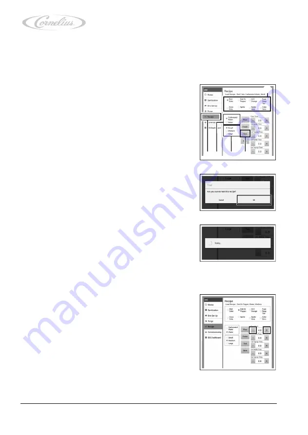
8.2.10

Checking and configuring settings in the “Recipe” menu

In the "Recipe" menu, the mixing ratio to the dispensing time can be checked and adjusted.

1.

Call up the “VMC Settings” menu (virtual machine control settings); see the document

“Tower operator manual”, document no. TD0000000

.

2.

Check the mixing ratio to the dispensing time as follows:

a.

Press “Recipe” (Figure 92/5).

b.

Select a product by pressing the required one.
(Figure 92/1).

c.

Press the basic ingredient to select it according
to the chosen product (Figure 92/4).

d.

Select the cup size (Figure 92/3) you wish to
check.

e.

Place a cup under the dispensing nozzle.

f.

Press “Test” (Figure 92/2).

A new window opens.

g.

Confirm the window message by pressing “OK”.

The selected beverage is dispensed.

h.

Check the mixing ratio for all products and cup
sizes.

If the settings are correct, return to the ser-
vice menu and continue with the next step,

Chapter 8.2.11, page 70

.

If the settings are not correct, you can set
the mixing ratio to the dispensing time as follows:

1.

Increase or reduce the dispensing time using “+” or “-”.

2

1

3

4

5

Figure 92

Figure 93

Figure 94

Figure 95

Summary of Contents for 221000414x

Page 1: ...Installation and service manual Postmix tower Ribbon...

Page 2: ...istribution and utilisation of this document as well as the communication of its contents is prohibited unless expressly permitted Violations shall result in an obligation to pay damages All rights re...

Page 3: ...Transport and packaging 7 2 1 Storage 7 2 2 Disposal 8 3 Description 9 3 1 Assemblies and components 9 3 2 Functions within the dispensing system 11 3 3 Functions of the unit 11 3 4 Touchscreen softw...

Page 4: ...13 Replacing the valves 54 7 14 Replacing the automatic circuit breakers 56 8 Commissioning shutdown 58 8 1 Commissioning 59 8 2 Configuration 61 8 2 1 Software installation 61 8 2 2 Checking settings...

Page 5: ...ler menu 80 8 2 22 Checking and configuring the Date Time Setting menu 83 8 2 23 Checking and configuring the Language menu 83 8 2 24 Calling up and configuring the Machine Configuration menu 84 8 2 2...

Page 6: ...e for which Cornelius assumes no liability Im proper use of the unit is prohibited You can find further information about the improper use of the unit and the meaning of im proper use in the tower ope...

Page 7: ...work 1 5 2 Safety information for using electrical assemblies Danger To prevent risks to health and safety please always observe the following five safety rules 1 Disconnect from power 2 Secure agains...

Page 8: ...s When fixing cables in place using cable ties observe the following points Once work on the product is completed return the area to the same state that you found it in Using cable ties combines cable...

Page 9: ...ble storage temperature is 10 C to 50 C The acclimatisation period is 6 hours Caution Component damage due to freezing liquids Ambient temperatures that are below freezing will lead to the freezing of...

Page 10: ...the at mosphere Caution Risk of electrostatic charge Improper handling or storage may result in electrostatic charges If possible store units and or any electronic components in their original packagi...

Page 11: ...removed for servicing purposes and can be attached to the housing in such a way that it remains functional during service operations while simultaneously allowing access to the in ternal assemblies Th...

Page 12: ...ozzle housing 2 Diffusor 3 Diffusor seal 4 Diffusor O ring The drain set assembly comprises the following components 1 Drain fitting 2 O ring 3 Flat seal 4 Fastening nut 5 Tube 6 Tubing clamp 7 Insula...

Page 13: ...t Valve control takes place via the unit s control electronics and depends on the inputs made via the touchscreen The beverage components flowing from the valves are supplied to the diffusor where the...

Page 14: ...hscreen software 1 BRANDS 2 FLAVOUR flavour shot 3 SODA carbonated water 4 POUR 5 Cup sizes 1 PIN input 1 VMC Settings virtual machine control settings 2 HMI Status user interface status 3 Software UI...

Page 15: ...Document no TD0000100 Version 06 11 2017 Index 0 1 Product Price 2 Enable Disable Product 3 UI Template Scheduler 4 Date Time Setting 5 Language 6 Machine Configuration 7 Disable Touch for Cleaning 8...

Page 16: ...rage 10 to 50 C Operating environ ment 10 to 32 C System output Syrup 8 Flavour shot 4 Power supply 230 50 V Hz Max output 70 W Supply requirements Max pressure 100 water 70 syrup PSI Min pressure 40...

Page 17: ...supply 115 230 V 50 60 Hz Max output 60 W 4 A Protection class I IP 21 Connection Type pin assignment Carbonated water inlet 3 8 inch inside diameter 1 2 inch outside diameter Carbonated water return...

Page 18: ...s Deutschland GmbH Document no TD0000100 Version 06 11 2017 Index 0 Cable 220046667 Promate computer cable for touchscreen and ADA keyboard optional Cable 220046670 DC 24 V output still water control...

Page 19: ...i ance with safety information Failure to observe the safety information will result in a risk of bringing about operating conditions at the unit which may cause personal injury or equipment damage Pl...

Page 20: ...7504 EU Figure 10 2 of the E Box Figure 10 1 from the mains supply see chapter A 3 page 99 3 Disconnect the plug cable no 220046667 Figure 10 3 from the E Box Figure 10 1 see chapter A 3 page 99 4 Wai...

Page 21: ...n into the service position 1 Undo the fastening screws Figure 11 1 on the touch screen to maximum stop 2 Pull the touchscreen assembly out of the unit 3 Raise and then mount the touchscreen Figure 13...

Page 22: ...asures and information instructions see chapter 1 page 4 Notice All installation maintenance and repair work at the unit is to be carried out by an expert only Warning Risk of personal injury and equi...

Page 23: ...n to allow trained staff to supervise Notice Observe all rules and regulations regarding installation rooms and electric connections as applicable in the individual countries as well as accident preve...

Page 24: ...plate 5 Saw the opening for the tubes and cables into the supporting structure as indicated on the drill template 6 Remove any dirt or dust from the supporting structure Prerequisites Reference The lo...

Page 25: ...page 99 E Box cable diagram 220046683 1 see chapter A 4 page 100 Tower operator manual Document no TD0000000 1 Notice The assembly and installation of the E Box must not be carried out in wet or humid...

Page 26: ...chland GmbH Document no TD0000100 Version 06 11 2017 Index 0 1 Attach the E Box Figure 14 2 using the fastening screws Figure 14 1 Observe the installation mounting direction Figure 14 3 2 Connect the...

Page 27: ...668 1 see chapter A 3 page 99 E Box cable diagram 220046683 1 see chapter A 4 page 100 Tower operator manual Document no TD0000000 1 Undercounter cooler instal lation and service manual Document no va...

Page 28: ...he unit is properly attached After attach ment the unit must not tilt or overturn 4 Remove the caps from all tubes 5 Connect all tubes Figure 18 1 to the python Figure 18 2 using push in fittings Obse...

Page 29: ...see chapter 8 1 page 59 5 5 Installing the drain set Figure 20 1 2 3 Prerequisites Reference The unit has been installed see chapter 5 4 page 25 Required tools materials ID Reference Qty amount Comme...

Page 30: ...he O ring through the opening Figure 22 2 of the drip tray Figure 22 3 3 Slide the flat seal Figure 23 2 onto the drain fitting Figure 23 4 from below all the way to the base plate Figure 23 1 4 Attac...

Page 31: ...move the threaded bolts Figure 26 3 nuts Figure 26 1 and washers Figure 26 2 used to attach the unit to the supporting structure Prerequisites Reference The undercounter cooler has been shut down See...

Page 32: ...rting structure in an upward motion 6 Lift the unit and seal off the supporting structure and pack it as described in chapter 2 page 7 5 7 Removing the E Box 1 Remove the fastening screws Figure 28 1...

Page 33: ...the tube Figure 29 3 from the drain fitting Figure 29 1 2 Remove the fastening nut Figure 30 3 with the flat seal Figure 30 2 from the drain fitting Figure 30 4 3 Pull out the drain fitting Figure 31...

Page 34: ...d information instructions see chapter 1 page 4 Notice All installation maintenance and repair work at the unit is to be carried out by an expert only Warning Risk of personal injury and equipment dam...

Page 35: ...omponents Action Daily Tower outside Clean See the document Tower operator manual document no TD0000000 Daily Tower outside Perform a visual inspection See the document Tower operator manual document...

Page 36: ...g starts with the first tube being rinsed with water for 3 minutes 6 Rinse all tubes one after the other with water by select ing the products one after the other You can only continue to the next ste...

Page 37: ...e must be no less than 15 minutes In the third step the tubes will be rinsed with clear water 11 Fill the cleaning container with clear water 12 Select the three required products by pressing the rele...

Page 38: ...GmbH Document no TD0000100 Version 06 11 2017 Index 0 18 To close the service menu press Exit Maintenance Page 19 Confirm the window message by pressing OK 20 Select each product until the beverage is...

Page 39: ...s 1 Check the diffusor seal for damage and elasticity Replace any damaged diffusor seals see chapter 7 3 page 42 2 Check the nozzle seal Figure 38 1 for damage Prerequisites Reference The diffusor sea...

Page 40: ...17 Index 0 6 4 Lubricating the nozzle seal 1 Relubricate the nozzle seal Figure 39 1 by applying sufficient lubricating grease to the circumference Prerequisites Reference The panel has been removed s...

Page 41: ...formation instructions see chapter 1 page 4 Notice All installation maintenance and repair work at the unit is to be carried out by an expert only Warning Risk of personal injury and equipment damage...

Page 42: ...unit 3 Insert the new nozzle housing into the unit making sure it is straight 4 Lock the nozzle housing into the unit by turning Make sure that the dispensing nozzle is inserted cor rectly as otherwi...

Page 43: ...diffusor down and out of the unit 2 Position the new diffusor within the unit 3 Push the diffusor up into the unit Finishing tasks 1 Install the nozzle carrier see chapter 7 1 page 40 Prerequisites R...

Page 44: ...diffusor seal from the diffusor 2 Insert a new diffusor seal into the diffusor Ensure correct positioning coding of the diffusor seal within the diffusor Finishing tasks 1 Install the diffusor see ch...

Page 45: ...acing the panel 1 Remove the panel from the unit 2 Attach the new panel Finishing tasks 1 Install the diffusor see chapter 7 2 page 41 Prerequisites Reference The diffusor has been removed see chapter...

Page 46: ...chapter 5 8 page 31 2 Install the new drain set see chapter 5 5 page 27 Finishing tasks 1 Install the grill see chapter 7 6 page 45 Prerequisites Reference The grill has been removed see chapter 7 6...

Page 47: ...ill 1 Remove the grill from the drip tray 2 Remove the drip tray from the unit 3 Attach the new drip tray 4 Insert the grill in the drip tray Finishing tasks 1 Install the panel see chapter 7 4 page 4...

Page 48: ...roller board and touchscreen panel 1 Undo the fastening screws Figure 51 1 on the touch screen to the end stop 2 Pull the touchscreen assembly out of the unit Prerequisites Reference The panel has bee...

Page 49: ...onnect the plugs Figure 55 2 and 3 from the unit controller board 11 Lift and remove the touchscreen cover Figure 55 1 When removing the touchscreen cover Figure 55 1 pull out all disconnected cables...

Page 50: ...ntroller board 22 Position the touchscreen within the unit 23 Attach the touchscreen using the fastening screws Figure 51 1 Finishing tasks 1 Install the panel see chapter 7 4 page 43 7 8 Replacing th...

Page 51: ...Figure 58 1 2 Lift off the side sections Figure 58 1 3 Position the new side sections Figure 58 1 on the unit 4 Attach the side sections Figure 58 1 using the fastening screws Figure 58 2 Finishing t...

Page 52: ...e 60 2 5 Position the new valve controller board Figure 60 2 over the expansion plugs Figure 60 1 6 Attach the valve controller board Figure 60 2 by press ing the valve controller board Figure 60 2 on...

Page 53: ...ening screws Figure 61 3 on the housing Figure 61 2 3 Lift the housing Figure 61 2 off the unit 4 Position the new housing Figure 61 2 over the unit 5 Attach the housing Figure 61 2 using fastening sc...

Page 54: ...e top of the valve assembly Figure 62 2 2 Remove the fastening screws Figure 63 1 from the valve assembly Figure 63 2 3 Press the closing pistons Figure 63 4 and the closing plate Figure 63 3 up until...

Page 55: ...mbly Figure 65 1 for damage Replace any damaged quad rings Figure 65 2 6 Lubricate all quad rings Figure 65 2 of the valve assembly Figure 65 1 7 Position the valve assembly within the unit 8 Attach t...

Page 56: ...gure 67 2 3 Lift and remove the valve Figure 68 1 from the valve assembly Figure 68 2 in an upward motion Prerequisites Reference The valve assembly has been removed see chapter 7 12 page 52 Spare par...

Page 57: ...igure 69 1 on the valve for proper fit Adjust the fit of the quad rings Figure 69 2 and O rings Figure 69 1 as needed 7 Grease the quad rings Figure 69 2 and the O rings Figure 69 1 on the valve befor...

Page 58: ...rews Figure 72 1 that keep the lid Figure 72 2 of the E Box Figure 72 3 in place 2 Disconnect all necessary plugs and cables from the automatic circuit breakers Figure 73 1 Prerequisites Reference The...

Page 59: ...a forward motion 4 Insert the automatic circuit breaker Figure 75 1 into the E Box Figure 75 2 5 Connect all necessary plugs and cables to the automatic circuit breakers Figure 73 1 6 Attach the cove...

Page 60: ...measures and information instructions see chapter 1 page 4 Notice All installation maintenance and repair work at the unit is to be carried out by an expert only Warning Risk of personal injury and eq...

Page 61: ...e the document Tower operator manual document no TD0000000 Prerequisites Reference The undercounter cooler has been put into service See the document Undercounter cooler installation and service manua...

Page 62: ...position I The unit will power up and the service menu will appear on the touchscreen If the unit does not power up see chapter 9 page 91 2 Touch the touchscreen 3 Clean the tubes and valves see chap...

Page 63: ...ed by Cornelius Deutschland GmbH will be borne by you Prerequisites Reference The latest UI update has been downloaded The Taptic3_Package is in the master directory on the USB stick The touchscreen i...

Page 64: ...ew UI package The unit s system will boot 8 2 2 Checking settings in the Current Version menu 1 Check the version see the document Tower operator manual document no TD0000000 If it is the latest versi...

Page 65: ...ace update see the document Tower opera tor manual document no TD0000000 A new window opens 4 Press USB Update The data will be updated If the USB stick is not automatically read proceed as follows a...

Page 66: ...s can be terminated with out any further consequences The update starts and the following statuses displayed on the touchscreen Copying TEMPLATE TPL to machine please wait Copying Setting files to mac...

Page 67: ...tings in the Wifi menu see chapter 8 2 15 page 76 7 Check the settings in the Critica_Aws menu see chapter 8 2 14 page 73 After the update is complete the Update Schedule application will be initiated...

Page 68: ...ITIZATION 3 Continue cleaning all tubes and valves see chapter 6 2 page 34 8 2 7 Checking and configuring settings in the Brix Set Up menu The valve assignment can be checked and configured in the Bri...

Page 69: ...document Tower opera tor manual document no TD0000000 During dispensing listen for a clicking sound coming from the valves If you can hear a clicking sound the beverage is being dispensed If you do no...

Page 70: ...lect a product by pressing the required one Figure 92 1 c Press the basic ingredient to select it according to the chosen product Figure 92 4 d Select the cup size Figure 92 3 you wish to check e Plac...

Page 71: ...en dispensing Proceed as follows 1 Using and or set a break in dispensing under 1st Settle Time Figure 96 1 2 Using and or set a dispensing time after a break under 1st Top Up Time Figure 96 2 A furth...

Page 72: ...tual machine control settings see the document Tower operator manual document no TD0000000 2 Press Commissioning 3 Check the values If the values are correct return to the service menu and continue wi...

Page 73: ...ion 06 11 2017 Index 0 c Either connect a new tank and tick From a rising main Figure 101 1 for the respective product or estimate the filling level and enter this select ing the unit of measurement F...

Page 74: ...000 2 Press BIB Dashboard If the values are correct return to the service menu and continue with the next step Chapter 8 2 13 page 72 If the values are not correct adjust the valve assign ment see cha...

Page 75: ...chapter 8 2 14 4 page 76 8 2 14 1 Calling up the Status menu In the Status menu you can register the unit or cancel the registration under the menu item Register Server Under the menu item Message Qu...

Page 76: ...the Status menu see chapter 8 2 14 1 page 73 2 Press Register Server A new window opens 3 Press SET Server Address A new window opens 4 Confirm the window message by pressing OK 5 Press Register This...

Page 77: ...Message menu 1 Call up the Status menu see chapter 8 2 14 1 page 73 2 Press Log Message If the indicator switches to OFF the Log Message menu has been deactivated By pressing Log Message again the ind...

Page 78: ...ation code 4 Confirm your input by pressing OK 8 2 14 4 Calling up the Cloud Recipe menu In the Cloud Recipe menu you can download the saved mixing ratios 1 Call up the Critica Aws menu see chapter 8...

Page 79: ...etwork 5 Select the required network by pressing the relevant option A new window opens 6 In this window you can remove the network by pressing Forget or connect to a network by pressing Connect Press...

Page 80: ...HCP Enabled option If the unit does not connect to the network when DHCP is en abled follow these steps a Remove the tick for the DHCP Enabled option b Press IP Address and enter the IP address c Pres...

Page 81: ...rd 4 Connect a USB stick to the unit 5 Press Download to download the system log A new window opens after the download has finished 6 Confirm the window message by pressing OK 7 Proceed with the next...

Page 82: ...e menu in the tower operator manual document no TD0000000 8 2 21 Calling up and configuring the UI Template Scheduler menu In the UI Template Scheduler menu you can create multiple user interfaces and...

Page 83: ...ivate the schedule by setting the slide button to ON 10 To edit a schedule for the previously selected weekday press the required schedule A new window opens 11 Press Edit A new window opens 12 Select...

Page 84: ...the day which you want to copy the schedule to 18 To delete a schedule for the previously selected week day press the required schedule A new window opens 19 Press Delete 20 To copy a schedule to all...

Page 85: ...2 22 Checking and configuring the Date Time Setting menu The Date Time Setting menu allows you to check and set the date and the time You can find further information about the menu in the tower opera...

Page 86: ...continue with the next step Chapter 8 2 25 page 84 If the settings are not correct select the required configuration A new window opens Confirm the window message by pressing Yes 8 2 25 Calling up th...

Page 87: ...et for a daily reboot 1 Call up the service menu see the document Tower operator manual document no TD0000000 2 Press Reboot Machine Setting 3 Press Reboot Machine Now to reboot the machine set tings...

Page 88: ...sign permissions to new users and edit the permissions of existing users 1 Call up the service menu see the document Tower operator manual document no TD0000000 2 Press User Management 3 To change the...

Page 89: ...the right or revoke the right to access the respective menu and make set tings there 8 Confirm your setting by pressing OK A new window opens 9 Confirm the window message by pressing OK 10 To delete a...

Page 90: ...etting by pressing OK A new window opens 18 Confirm the window message by pressing OK The new user will now appear in the list of added users 8 2 29 Adjusting the valves 1 Move the touchscreen into se...

Page 91: ...ge press Exit Maintenance Page 3 Confirm by pressing OK Notice The following describes how the unit is shut down by an expert for a longer period 24 hours If the unit is to be shut down temporarily 24...

Page 92: ...only CO2 comes out of the dispensing noz zle d Disconnect all basic ingredient beverage tubes of the undercounter cooler from the cleaning con tainer e Connect all basic ingredient beverage tubes to...

Page 93: ...measures and information instructions see chapter 1 page 4 Notice All installation maintenance and repair work at the unit is to be carried out by an expert only Warning Risk of personal injury and e...

Page 94: ...nt Tower opera tor manual document no TD0000000 Automatic circuit breaker on the E Box is defective Replace the automatic circuit breaker see chapter 7 14 page 56 Tower is not switched on Turn the key...

Page 95: ...oler installation and service manual Contaminated tubes Clean tubes see chapter 6 2 page 34 Only soda is being dispensed Fault or error on the undercounter cooler See the document Undercounter cooler...

Page 96: ...anual document no TD0000000 Adjust the valve see chapter 8 2 29 page 88 Too little too much syrup Check the flow setting for the affected product see the docu ment Tower operator manual document no TD...

Page 97: ...Index 0 Fault Probable cause Remedy USB stick is not recognised Formatting error Directory structure error Check the formatting Check the directory structure Use a new USB stick Notice Crushed ice in...

Page 98: ...A Applicable documents Installation and service manual Postmix tower Ribbon 96 Cornelius Deutschland GmbH Document no TD0000100 Version 06 11 2017 Index 0 A Applicable documents...

Page 99: ...A Applicable documents Installation and service manual Postmix tower Ribbon 97 Cornelius Deutschland GmbH Document no TD0000100 Version 06 11 2017 Index 0 A 1 Drill template...

Page 100: ...ation and service manual Postmix tower Ribbon 98 Cornelius Deutschland GmbH Document no TD0000100 Version 06 11 2017 Index 0 A 2 Flowchart S syrup Still still water Cin carbonated water input Cout car...

Page 101: ...A Applicable documents Installation and service manual Postmix tower Ribbon 99 Cornelius Deutschland GmbH Document no TD0000100 Version 06 11 2017 Index 0 A 3 Tower cable diagram...

Page 102: ...A Applicable documents Installation and service manual Postmix tower Ribbon 100 Cornelius Deutschland GmbH Document no TD0000100 Version 06 11 2017 Index 0 A 4 E Box cable diagram...

Page 103: ...www cornelius emea com Phone 49 0 21 73 79 3 0 Fax 49 0 21 73 77 4 38 Email info cornelius com Cornelius Deutschland GmbH Carl Leverkus Str 15 40764 Langenfeld Germany...

Reviews: