62
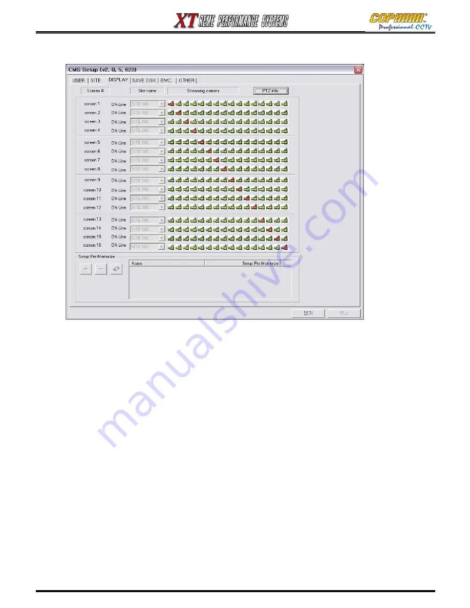
16-2-3 DISPLAY
From this Tab various OSD layouts can be created, and the cameras to be displayed in each
Screen Segment within each layout can be set. Each OSD layout is based on a 16-way split
screen.
For each individual Screen Segment a site must be selected from which a camera can be
selected to be displayed on the Layout. (e.g. If you have a DVR called 16CH-001, you must
select 16CH-001 from the drop-down list for each of the 16 screen segments – “screen 1” to
“screen 16”)
Once the Site Name has been assigned to each Screen Segment, a row of camera icons will
appear to the right (Four for XT04). Using the mouse, one camera icon on each line can be
selected (highlighted in Red) to be displayed in that segment.
When all the above has been selected, this OSD Layout can be saved.
Click with the mouse on the (+) button, and an entry will appear in the adjacent window.
Click on the Name (“to rename click here”) twice, slowly. Then you will be able to type in a name
for this OSD display set-up. This display can then be easily accessed in the future.
PTZ info. button : If the selected camera is a PTZ camera and is to be used, click this button to
check the camera information.
16. CMS
Summary of Contents for XT Series
Page 1: ...4 Channel DVR manual Rev 2 2 September 2006 XT Series ...
Page 20: ...20 3 SETUP ...
Page 70: ...70 ...


