


EMS-96
Instruction Manual
IM1200-U v1.6
Pag. 12 / 48
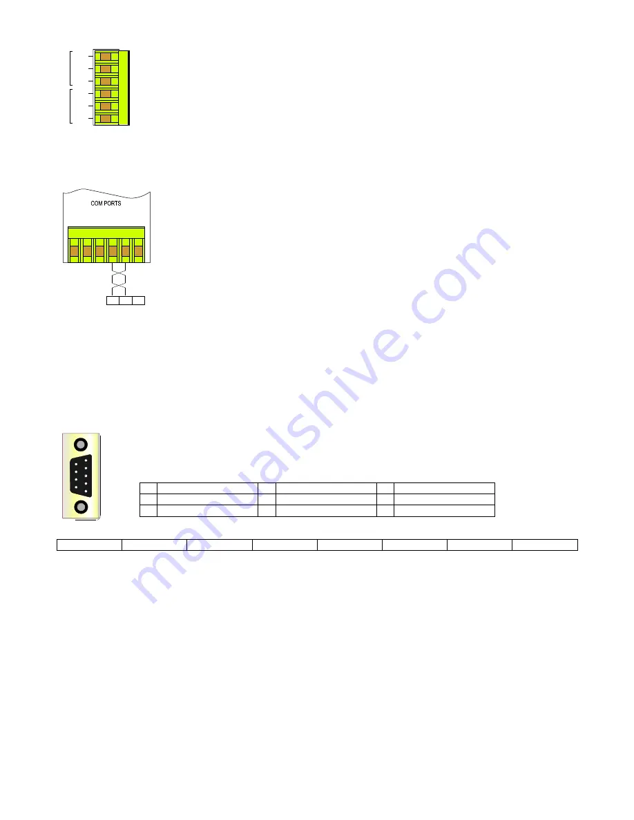
Serial ports (option)
Depending on the version, the instrument can be equipped with one or two isolated half duplex RS485 serial
interface.
Two options are available:
1 serial port RS485
2 serial ports RS485
With these options the instrument can communicate with the external with the
Modbus protocol
. The two
ports are independent and they can perform the same operations. The presence of the serial port RS485
allows the
software update
.
COM1
A1: +data
B1: -data
C1: common
COM2
A2: +data
B2: -data
C2: common
The instrument communicates via a asynchronous isolated serial interface in the standard RS485 Half-
duplex that allows a connection in a network up to 247 nodes. This allows to implement a
communication network between different instruments and a master unit (data concentrator) for a
detailed control of an electrical installation.
The maximum length of the line depends on variables such as the transmission rate and characteristics
of the cables used. It’s recommend to use a shielded twisted pair cable with low attenuation, with a
minimum section of 0.36mm
2
(22AWG) and capacity of less than 60pF / m.
The maximum length is about 1200m. For longer distances it’s need to use signal amplifiers (repeaters).
High networking length and/or where environments are electrically "noisy", it requires the use of two
termination resistors (at the beginning and end of the line) of 100-120Ω. The use of repeaters is also
necessary in the case of networks with more than 32 nodes.
At each repeater can be connected 32 units.
Please note that complex networks with large number of nodes cause a slower speed of response by
the instruments.
Connection type: half-duplex (2 wires + common).
Isolation: opto-couples (3750 Vrms min.).
In the figure is showed a connection with a not shielded cable. In the shielded cable connection it’s necessary to connect the
shield to COM terminal.
Profibus port (option)
Profibus-DP is a multi-master systems. In the networks it’s possible to have up to 126 devices on the same bus. In
profibus-DP networks, the interchange of data between peripheral modules and the master is made automatically
by the profibus controller, which ‘virtualise’ the data exchange memory of the DP devices in the memory of the
master. In the following picture the pin-out of the Profibus-DP port:
The profibus interface detects automatically the baud rate of the network; the baud rate available are:
9.6 Kbit/s
19.2 Kbit/s
45.45 Kbit/s
93.75 Kbit/s
187.5 Kbit/s
500 Kbit/s
1.5 Mbit/s
3 Mbit/s
It’s possible to request to the manufacturer application examples, GSD files and protocol manual (IM157).
The 3 yellow led on the back have the following meanings:
-
instrument not parameterized: the 3 led turn on continuously in the sequence PAR - ExB - ExA
-
instrument parameterized: led PAR turned on
-
instrument parameterized and in communication: led PAR on, led ExA and ExB turn on independently
Service: port used by the manufacturer only.
1
Not connected
4
RTS
7
Not connected
2
Not connected
5
Gnd
8
RxD/TxD-N (A)
3
RxD/TxD-P (B)
6
Power Supply (+5V)
9
Not connected
A2
B2
C2
A1
B1
C1
C
O
M
2
-R
S
4
8
5
C
O
M
1
-R
S
4
8
5
EMS
C
1
A1
+
A2
+
B1
-
C
2
B2
-
Master
o
Concentrator
o
Other instrument
COM
A+
B-
1
5
6
9