CNT24-4(PCI)
I/O Ports and Registers
45
Notes!
- The default is "only the next Z-phase input is available." (04h)
- If ZSEL=1 (negative logic), a LOW Z-phase input is available.
- If the Z-phase/CLR input is not used, set ZE1=0 and ZE0=1
(Disable Z-phase input).
- If "only the next Z-phase input is available" is set and the
counter is zero-cleared with the Z-phase input, and if the counter
is cleared with RESET=0, "only the next Z-phase input is
available" will be set with the RESET=0.
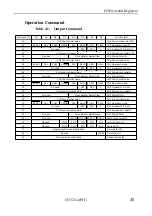
Comparison register
(Command CH0:03h, CH1:08h, CH2:0Dh, CH3:12h)
The counter value of the corresponding channel and the data in the
comparison register are compared. If they match, the status bit
"EQ" is set to 0. (As long as they match, the bit remains 0.) This
register is cleared when the bus is reset.
Output the command on the output port +0 and set the comparison
data on the output port +1. The comparison data is 24 bit data.
Output the data three times, eight bits at a time, from the lower bits,
the middle bits and the upper bits.
The following sample program shows how to set the counting
comparison value 1000 (3E8h) to CH1.
OUT 0h, 03h (CH1 : Select comparison register)
OUT 1h, E8h (Lower bits)
OUT 1h, 03h (Middle bits)
OUT 1h, 00h (Upper bits)
In addition, a particular setting can output a one-shot pulse.
(For more details, see "One-shot Pulse" description.)


