CNT24-4(PCI)
External Connection
29
Output Circuit and Connecting Example
When the count value of each channel and the user set value match,
the circuit outputs a matched signal for one shot (1 pulse). The
signal output part uses the open collector method by photocoupler
insulation. As a result, an external power source is needed to run
the board output.
Photocoupler
1k
Ω
Plus common
1k
Ω
External Power
Supply
DC5V~12V
Vcc
18k
Ω
Photocoupler
Load
Load
Output pin
Minus common
Figure 3.11. Output Circuit and Connecting Example
Note!
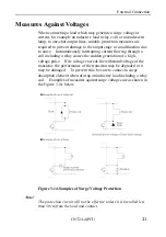
The board's output transistor does not have a surge voltage
protection circuit. As a result, to run inductive loads (for example,
relays and lamps), install surge voltage protection at the loading
side. See "Appendix C: Surge Voltage" for further information.


