External Connection
CNT24-4(PCI)
24
Connector
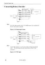
Connecting the CNT24-4(PCI) board to external devices is via one
37-pin female D-Type connector (CN1) and one 30-pin male
connector (CN2).
37
19
• Installed connector
37-pin D-Type connector (female)
• Suitable cable
17JE-23370-02(D8C) (male)
(DDK)
FDCD-37P (male)
(HIROSE)
DC-37P-N (male)
(Japan Aviation Electronics)
36
21
20
18
17
3
2
1
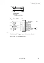
Figure 3.2. CN1 Connector as Viewed from Back of
Computer
Plus Common
General-purpose Input
OUT Z/CLR
OUT B/DOWN
OUT A/UP
Not Connected
General-purpose Input
OUT Z/CLR
OUT B/DOWN
OUT A/UP
Plus Common 2
Not Connected
Minus Common
CH3 Output
CH2 Output
CH1 Output
CH0 Output
Plus Common
19
18
17
16
15
14
13
12
11
10
9
8
7
6
5
4
3
2
1
37
36
35
34
33
32
31
30
29
28
27
26
25
24
23
22
21
20
P3P
P3U
P3Z
P3B
P3A
N.C.
P2U
P2Z
P2B
P2A
P2P
N.C.
OUTN
OUT3
OUT2
OUT1
OUT0
OUTP
N.C.
P1P
P1U
P1Z
P1B
P1A
N.C.
P0U
P0Z
P0B
P0A
P0P
N.C.
N.C.
N.C.
N.C.
N.C.
N.C.
N.C.
Not Connected
Not Connected
Plus Common 1
General-purpose Input
OUT Z/CLR
OUT B/DOWN
OUT A/UP
Not Connected
General-purpose Input
OUT Z/CLR
OUT B/DOWN
OUT A/UP
Plus Common 0
CH1
CH0
Count-equal
Plus Output
CH2
CH3
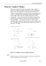
Note!
Each channel has an independent Plus Common.
Figure 3.3. CN1 Pin Assignments

