


20 - Hardware Installation
DeviceMaster PNIO | UP User Guide
: 2000639 Rev. A
Hardware Installation
4.
Verify that the
Status
LED has completed the boot cycle and network
connection for the DeviceMaster is functioning properly using the following
table.
Do not connect RS-422/485 devices until the IP address is configured
and an appropriate port interface type has been configured. The
default port setting is RS-232.
5.
Preparing the DeviceMaster for Configuration
on Page 23 for default
network settings and how to configure the DeviceMaster for use.
4-Port Panel Mount Installation
Use the following procedure to install the DeviceMaster 4-port.
1.
Optionally, attach the mounting brackets using the screws provided in the kit
(6-32 1/4” flathead machine) or place the DeviceMaster on a stable surface.
Failure to use the correct screws can damage the PCB and void the
warranty. Do NOT use screws that exceed the length of the screws
provided with the mounting bracket kit.
Note:
If you ordered the DeviceMaster Rackmount Shelf Kit accessory, use the
document that accompanied that kit or
to
mount the DeviceMaster on the shelf.
2.
Connect the DeviceMaster to the same Ethernet network segment as the PLC.
If the DeviceMaster serial number is below xxxx-030000 use one of the
following methods to connect the cable. Serial numbers above xxxx-030000,
the Ethernet port are interchangeable.
•
Ethernet hub or switch (10/100Base-T)
: Connect to the port labeled
UP
on the DeviceMaster using
a standard Ethernet cable.
•
Server NIC (10/100Base-T)
: Connect to the port labeled
DOWN
on the
DeviceMaster using
a standard Ethernet cable.
•
Daisy-chaining DeviceMaster
u
nits
: Connect the port labeled
DOWN
on
the first DeviceMaster to the port labeled
UP
on the second DeviceMaster
or other device using a standard Ethernet cable. Refer to
Note:
Your model provides two Ethernet ports, UP is the first port and DOWN
is the second port.
Note:
Do not connect multiple units until you have changed the default IP
address, see
Preparing the DeviceMaster for Configuration
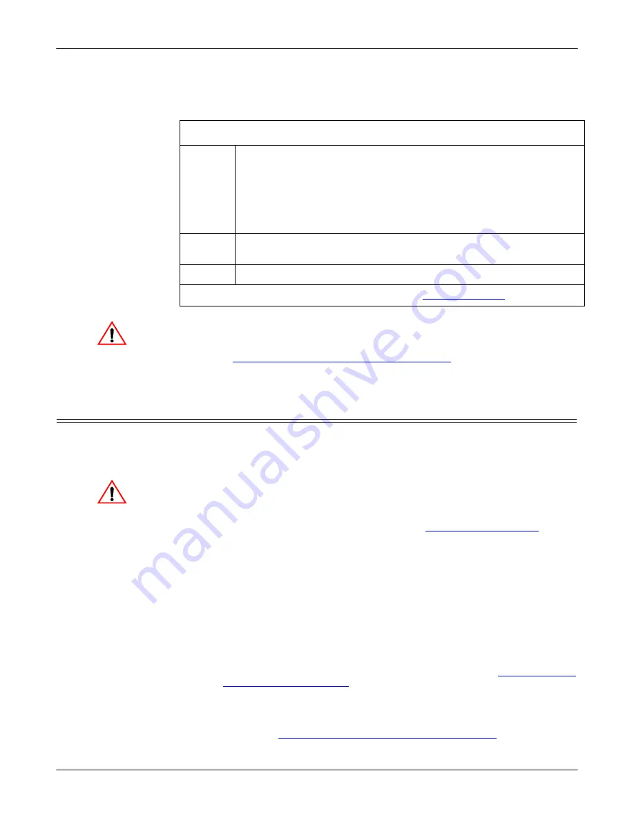
PNIO-2304 LED Descriptions
STATUS
The
STATUS
LED on the device is lit, indicating you have power and it
has completed the boot cycle.
Note:
The
Status
LED flashes while booting and it takes approximately
15 seconds for the Bootloader to complete the cycle.
When the
Bootloader completes the cycle, the LED flashes rapidly for
several times then stays off and blinks approximately every 10
seconds when there is no PLC connection
.
LINK
If the
LINK
(green) LED is lit, it indicates a working Ethernet
connection.
ACT
If the
ACT
(yellow) LED flashes, it indicates network activity.
Note:
For additional LED information, go to the
Caution
Caution