


16
DSL
Green
On
xDSL Link is established.
Off
The device is powered down.
Blink
xDSL Link is training.
ETH WAN
Green
On
Ethernet WAN is connected.
Off
Ethernet WAN is not connected.
Blink Ethernet WAN is transmitting/ receiving.
5G WiFi
Green
On
Wi-Fi enabled.
Off
Wi-Fi disabled.
Blink Data transmitting or receiving over WLAN.
2.4G WiFi
Green
On
Wi-Fi enabled.
Off
Wi-Fi disabled.
Blink Data transmitting or receiving over WLAN.
WPS
Green
On
WPS connection successful. The LED will stay on
for 3 minutes.
Off
No WPS association process ongoing.
Blink WPS connection in progress.
ETH 1X-4X
Green
On
An Ethernet Link is established.
Off
An Ethernet Link is not established.
Blink
Data transmitting or receiving over Ethernet.
USB
Green
On
At least one device is connected to the USB port.
Off
No device is connected to the USB port or a
device is connected to a USB port but not active.
Blink
Data TX/RX passing through at least one of the
USB ports.
POWER
Green
On
The device is powered up.
Off
The device is powered down.
Red
On
POST (Power On Self Test) failure or other
malfunction. A malfunction is any error of
internal sequence or state that will prevent the
device from connecting to the DSLAM or passing
customer data.
Note:
A malfunction is any error of internal sequence or state that will prevent the device
from connecting to the DSLAM or passing customer data. This may be identified at
various times such after power on or during operation through the use of self testing
or in operations which result in a unit state that is not expected or should not occur.
IP connected (the device has a WAN IP address from IPCP or DHCP and DSL is up or
a static IP address is configured, PPP negotiation has successfully complete – if used
– and DSL is up ) and no traffic detected. If the IP or PPPoE session is dropped for
any other reason, the light is turned off. The light will turn red when it attempts to
reconnect and DHCP or PPPoE fails.
Summary of Contents for VR-3071 Series
Page 1: ...261099 055 VR 3071 Series Home Gateway User Manual Version A1 0 January 10 2020...
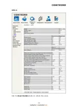
Page 24: ...23 This screen shows hardware software IP settings and other related information...
Page 31: ...30 ADSL2 Click the Reset Statistics button to refresh this screen...
Page 46: ...45 5GHz...
Page 52: ...51 List the associated station to the wireless interface...
Page 57: ...56 NOTE Up to 16 PVC profiles can be configured and saved in flash memory...
Page 68: ...67 5 3 3 UPnP Select the checkbox provided and click Apply Save to enable UPnP protocol...
Page 71: ...70 A maximum of 100 entries can be added to the URL Filter list...
Page 86: ...85...
Page 106: ...105...
Page 130: ...129 2 Both devices need to have the same fixed channel See section 6 12 6 Advanced for details...
Page 134: ...133 6 12 6 Advanced This page allows you to configure the Physical Wireless interfaces 2 4GHz...
Page 136: ...135...
Page 168: ...167 STEP 2 Click the Windows start button Then select Control Panel...
Page 169: ...168 STEP 3 Select Devices and Printers STEP 4 Select Add a printer...
Page 197: ...196 F2 4 PPP over ATM PPPoA IPv4 STEP 1 Click Next to continue...
Page 200: ...199 Click Next to continue or click Back to return to the previous step...
Page 213: ...212 After clicking Apply Save the new service should appear on the main screen...


