background image


156 

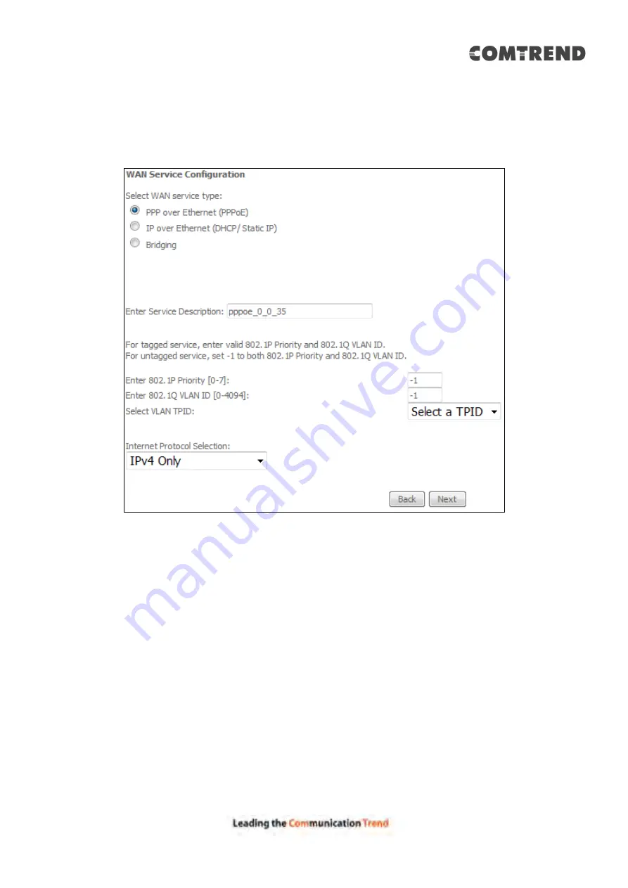
E2.1 PPP over ETHERNET (PPPoE) 

 IPv4 

STEP 1: 

Select the PPP over Ethernet radio button and click 

Next

. You can also 

enable IPv6 by ticking the checkbox 

 at the bottom of this screen. 


For tagged service, enter valid 802.1P Priority and 802.1Q VLAN ID. 
 
For untagged service, set -1 to both 802.1P Priority and 802.1Q VLAN ID 


Select a TPID if VLAN tag Q-in-Q is used. 


STEP 2: 

On the next screen, enter the PPP settings as provided by your ISP.   
Click 

Next

 to continue or click 

Back 

to return to the previous step. 


Summary of Contents for AR-5319

Page 1: ...AR 5319 ADSL2 WLAN Router User Manual 261056 079 Version A1 1 March 6 2017...

Page 2: ...e g a wet basement Do not connect the power supply cord on elevated surfaces Allow it to lie freely There should be no obstructions in its path and no heavy items should be placed on the cord In addi...

Page 3: ...d receiver Connect the equipment into an outlet on a circuit different from that to which the receiver is connected Consult the dealer or an experienced radio TV technician for help This Class B digit...

Page 4: ...etween the radiator your body This transmitter must not be co located or operating in conjunction with any other antenna or transmitter Cet quipement est conforme avec l exposition aux radiations ISED...

Page 5: ...ILITY or FITNESS FOR A PARTICULAR PURPOSE See the GNU General Public License for more details You should have received a copy of the GNU General Public License along with this program If not see http...

Page 6: ...o 33 4 8 2 IPv6 Neighbor 34 4 8 3 IPv6 Route 35 4 9 CPU MEMORY 36 4 10 NETWORK MAP 37 4 11 WIRELESS 38 4 11 1 Station Info 38 4 11 2 Site Survey 39 CHAPTER 5 BASIC SETUP 40 5 1 LAYER 2 INTERFACE 40 5...

Page 7: ...6 9 CERTIFICATE 95 6 9 1 Local 95 6 9 2 Trusted CA 97 6 10 POWER MANAGEMENT 98 6 11 MULTICAST 99 6 12 WIRELESS 101 6 12 1 Basic 101 6 12 2 Security 103 6 12 3 WPS 106 6 12 4 MAC Filter 109 6 12 5 Wir...

Page 8: ...7 CHAPTER 9 LOGOUT 137 APPENDIX A FIREWALL 138 APPENDIX B PIN ASSIGNMENTS 141 APPENDIX C SPECIFICATIONS 142 APPENDIX D SSH CLIENT 144 APPENDIX E CONNECTION SETUP 145 APPENDIX F PRINTER SERVER 201...

Page 9: ...Ethernet ports a Wi Fi Protected Setup WPS Wi Fi switch button a USB Host and is backward compatible with existing 802 11b 11Mbps and 11g 54bps equipment The AR 5319 ADSL2 router provides state of the...

Page 10: ...n be used USB HOST PORT A USB 2 0 host port supports compatible printers See Appendix F for setup instructions If a storage device is connected to the USB host port it can be used to stream the DLNA s...

Page 11: ...e Power LED displays as expected then the device is ready for setup see section LED Indicators Caution 1 If the device fails to power up or it malfunctions first verify that the power cords are connec...

Page 12: ...failure WiFi Green On The wireless module is ready i e installed and enabled Off The wireless module is not ready i e either not installed or disabled Blink Data transmitting or receiving over WIFI US...

Page 13: ...nected the device has a WAN IP address from IPCP or DHCP and DSL is up or a static IP address is configured PPP negotiation has successfully complete if used and DSL is up and no traffic detected If t...

Page 14: ...he factory default configuration can be restored either by pushing the reset button for more than ten seconds until the power indicates LED blinking or by clicking the Restore Default Configuration op...

Page 15: ...14 STEP 4 Click OK to submit these settings If you experience difficulty with DHCP mode you can try static IP mode instead...

Page 16: ...your OS support documentation for further details STEP 1 From the Network Connections window open Local Area Connection You may also access this screen by double clicking the Local Area Connection ico...

Page 17: ...ttp 192 168 1 1 NOTE For local administration i e LAN access the PC running the browser must be attached to the Ethernet and not necessarily to the device For remote access i e WAN use the IP address...

Page 18: ...17 STEP 3 After successfully logging in for the first time you will reach this screen You can also reach this page by clicking on the following icon located at the top of the screen...

Page 19: ...The menu items shown are based upon the configured connection s and user account privileges For example if NAT and Firewall are enabled the main menu will display the NAT and Security submenus If eith...

Page 20: ...status Igmp Pxy Shows Internet Group Management Protocol IGMP proxy status Igmp Src Enbl Shows the status of WAN interface used as IGMP source MLD Pxy Shows Multicast Listener Discovery MLD proxy stat...

Page 21: ...15 seconds Click Reset Statistics to perform a manual update 4 2 1 LAN Statistics This screen shows data traffic statistics for each LAN interface Heading Description Interface LAN interface s Receive...

Page 22: ...ffic statistics for each WAN interface Heading Description Interface WAN interfaces Description WAN service label Received Transmitted Bytes Pkts Errs Drops Number of Bytes Number of Packets Number of...

Page 23: ...tted over the interface In Packets Number of packets received over the interface Out Packets Number of packets transmitted over the interface In OAM Cells Number of OAM Cells received over the interfa...

Page 24: ...23 4 2 4 xDSL Statistics The xDSL Statistics screen displays information corresponding to the xDSL type The two examples below ADSL2 ADSL2 show this variation ADSL2...

Page 25: ...Status Shows the status of PhyR Physical Layer Re Transmission impulse noise protection Line Coding Trellis Trellis On Off SNR Margin 0 1 dB Signal to Noise Ratio SNR margin Attenuation 0 1 dB Estimat...

Page 26: ...ors RS Correctable Errors Total Number of RS with correctable errors RS Uncorrectable Errors Total Number of RS words with uncorrectable errors HEC Errors Total Number of Header Error Checksum errors...

Page 27: ...26 Click Start to start the test or click Close to cancel the test After the BER testing is complete the pop up window will display as follows...

Page 28: ...27 xDSL TONE GRAPH Click Draw Graph on the xDSL Statistics screen and a pop up window will display the xDSL bits per tone status as shown below...

Page 29: ...ination Flag U route is up reject route G use gateway H target is a host R reinstate route for dynamic routing D dynamically installed by daemon or redirect M modified from routing daemon or redirect...

Page 30: ...ddress Shows the MAC address of host pc Device Shows the connection interface 4 5 DHCP Click DHCP to display all DHCP Leases Field Description Hostname Shows the device host PC network name MAC Addres...

Page 31: ...iption IPv6 Address Shows IP address of device host PC MAC Address Shows the Ethernet MAC address of the device host PC Duration Shows leased time in hours Expires In Shows how much time is left for e...

Page 32: ...urce IP The source IP from which the NAT session is established Source Port The source port from which the NAT session is established Destination IP The IP which the NAT session was connected to Desti...

Page 33: ...ction Field Description Interface The Source interface from which the IGMP report was received WAN The WAN interface from which the multicast traffic is received Groups The destination IGMP group addr...

Page 34: ...nabled Status Connection status of the WAN interface Address IPv6 Address of the WAN interface Prefix Prefix received configured on the WAN interface Device Link local Address The CPE s LAN Address De...

Page 35: ...to display the list of IPv6 nodes discovered Field Description IPv6 Address Ipv6 address of the device s found Flags Status of the neighbor device HW Address MAC address of the neighbor device Device...

Page 36: ...k IPv6 Route to display the IPv6 route info Field Description Destination Destination IP Address Gateway Gateway address used for destination IP Metric Metric specified for gateway Interface Interface...

Page 37: ...36 4 9 CPU Memory Displays the system performance graphs Shows the current loading of the CPU and memory usage with dynamic updates Note This graph is unavailable for Internet Explorer users...

Page 38: ...37 4 10 Network Map The network map is a graphical representation of router s wan status and LAN devices The feature is only available using a non IE browser...

Page 39: ...ions that are associated with the Access Point along with the amount of time since packets were transferred to and from each station If a station is idle for too long it is removed from this list Auth...

Page 40: ...39 4 11 2 Site Survey The graph displays wireless APs found in your neighborhood by channel...

Page 41: ...screen 5 1 Layer 2 Interface Add or remove ATM PTM and ETH WAN interface connections here Click Add to create a new ATM interface see Appendix E Connection Setup NOTE Up to 8 ATM interfaces can be cre...

Page 42: ...anagement Protocol IGMP Proxy status IGMP Source Shows the status of WAN interface used as IGMP source NAT Shows Network Address Translation NAT status Firewall Shows the Security status IPv6 Shows th...

Page 43: ...identified by Protocol and External port to the internal server with private IP addresses on the LAN side The Internal port is required only if the external port needs to be converted to a different...

Page 44: ...d the port ranges are automatically configured Protocol TCP TCP UDP or UDP Internal Port Start Enter the internal port starting number when you select Custom Server When a service is selected the port...

Page 45: ...n application is selected the port ranges are automatically configured Trigger Port End Enter the ending trigger port number when you select custom application When an application is selected the port...

Page 46: ...figured in the Virtual Servers table to the DMZ host computer To Activate the DMZ host enter the DMZ host IP address and click Save Apply To Deactivate the DMZ host clear the IP address field and clic...

Page 47: ...he beginning of the public IP Public End IP The ending of the public IP Remove Remove this rule Click the Add button to display the following Select a Service then click the Save Apply button One to O...

Page 48: ...gh Supports ALG Pass through for the listed protocols To allow deny the corresponding ALG protocol select Enable Disable and then click the Save button After reboot the protocol will be added removed...

Page 49: ...y Save Consult the field descriptions below for more details GroupName Select an Interface Group 1st LAN INTERFACE IP Address Enter the IP address for the LAN port Subnet Mask Enter the subnet mask fo...

Page 50: ...and the Leased Time This setting configures the router to automatically assign IP default gateway and DNS server addresses to every PC on your LAN Setting TFTP Server Enable by ticking the checkbox Th...

Page 51: ...The remote DHCP server will provide the IP address 2ND LAN INTERFACE To configure a secondary IP address tick the checkbox outlined in RED below IP Address Enter the secondary IP address for the LAN p...

Page 52: ...51 5 3 1 LAN IPv6 Autoconfig Configure the LAN interface settings and then click Save Apply Consult the field descriptions below for more details...

Page 53: ...ns Heading Description Stateless Use stateless configuration Refresh Time sec The information refresh time option specifies how long a client should wait before refreshing information retrieved from D...

Page 54: ...le ULA Prefix Advertisement Allow RADVD to advertise Unique Local Address Prefix Randomly Generate Use a Randomly Generated Prefix Statically Configure Prefix Specify the prefix to be used Statically...

Page 55: ...ve to apply and save the settings Heading Description IP Version The IP version used for the neighbor device IP Address Define the IP Address for the neighbor device MAC Address The MAC Address of the...

Page 56: ...55 5 3 3 UPnP Select the checkbox provided and click Apply Save to enable UPnP protocol...

Page 57: ...ork from active scans set the wireless network name also known as SSID and restrict the channel set based on country requirements Click Apply Save to apply the selected wireless options Consult the ta...

Page 58: ...twork name SSID stands for Service Set Identifier All stations must be configured with the correct SSID to access the WLAN If the SSID does not match that user will not be granted access BSSID The BSS...

Page 59: ...stands for Service Set Identifier All stations must be configured with the correct SSID to access the WLAN If the SSID does not match that client will not be granted access Network Authentication This...

Page 60: ...station to alter frame bits thus avoiding disclosure to eavesdroppers Under shared key authentication each wireless station is assumed to have received a secret shared key over a secure channel that i...

Page 61: ...ction 8 5 Internet Time so that the scheduled times match your local time Click Add to display the following screen See below for field descriptions Click Apply Save to add a time restriction User Nam...

Page 62: ...Exclude radio button to deny access to the websites listed Tick the Include radio button to restrict access to only those listed websites Then click Add to display the following screen Enter the URL a...

Page 63: ...62 5 6 Home Networking 5 6 1 Print Server This page allows you to enable or disable printer support Please reference Appendix F to see the procedure for enabling the Printer Server...

Page 64: ...like pictures music and video to other LAN devices from the digital media server Insert USB drive to the USB host port on the back of router Modify media library path to the corresponding path of the...

Page 65: ...64 5 6 3 Storage Service This page displays storage devices attached to USB host Display after storage device attached for your reference...

Page 66: ...ection function is used for CPE to detect WAN service for either ETHWAN or xDSL interface The feature is designed for the scenario that requires only one WAN service in different applications The Auto...

Page 67: ...66 Enter the PPP username password given by your service provider for PPP service detection...

Page 68: ...red services and select disable to ignore any of those services to meet their own requirement and also reduce the detection cycle WAN services list for PTM mode A maximum of 7 WAN services with corres...

Page 69: ...o meet their deployed requirements Auto Detection status and Restart The Auto detection status is used to display the real time status of the Auto detection feature The Restart button is used to detec...

Page 70: ...THWAN port is not detected the Auto Detection for ETHWAN will be configured to the 4th LAN port by default and allows it to be configured for any LAN port as well 3 For cases in which both the DSL por...

Page 71: ...t one limiting condition For individual IP packets to pass the filter all conditions must be fulfilled NOTE This function is not available when in bridge mode Instead MAC Filtering performs a similar...

Page 72: ...range Destination IP address Enter destination IP address Destination Port port or port port Enter destination port number or range INCOMING IP FILTER By default all incoming IP traffic is blocked but...

Page 73: ...ort number or range At the bottom of this screen select the WAN and LAN Interfaces to which the filter rule will apply You may select all or just a subset WAN interfaces in bridge mode or without fire...

Page 74: ...WARDED means that all MAC layer frames will be FORWARDED except those matching the MAC filter rules BLOCKED means that all MAC layer frames will be BLOCKED except those matching the MAC filter rules T...

Page 75: ...Field Description Protocol Type PPPoE IPv4 IPv6 AppleTalk IPX NetBEUI IGMP Destination MAC Address Defines the destination MAC address Source MAC Address Defines the source MAC address Frame Direction...

Page 76: ...o activate QoS QoS and DSCP Mark are defined as follows Quality of Service QoS This provides different priority to different users or data flows or guarantees a certain level of performance to a data...

Page 77: ...ton The Enable button will scan through every queues in the table Queues with enable checkbox checked will be enabled Queues with enable checkbox un checked will be disabled The enable checkbox also s...

Page 78: ...o a specific network interface QoS enabled After selecting an Interface the following will be displayed The precedence list shows the scheduler algorithm for each precedence level Queues of equal prec...

Page 79: ...78 6 3 2 Wlan Queue Displays the list of available wireless queues for WMM and wireless data transmit priority...

Page 80: ...an entry from the list click Remove This screen creates a traffic class rule to classify the upstream traffic assign queuing priority and optionally overwrite the IP header DSCP byte A rule consists o...

Page 81: ...MAC Mask This is the mask used to decide how many bits are checked in the Destination MAC Address Classification Results Specify Egress Interface Choose the egress interface from the available list Sp...

Page 82: ...menu options are shown but ineffective 6 4 1 Default Gateway Default gateway interface list can have multiple WAN interfaces served as system default gateways but only one will be used according to t...

Page 83: ...After clicking Add the following will display IP Version Select the IP version to be IPv4 Destination IP address prefix length Enter the destination IP address Interface select the proper interface fo...

Page 84: ...e one On the following screen complete the form and click Apply Save to create a policy Field Description Policy Name Name of the route policy Physical LAN Port Specify the port to use this route poli...

Page 85: ...84 6 4 4 RIP To activate RIP configure the RIP version operation mode and select the Enabled checkbox for at least one WAN interface before clicking Save Apply...

Page 86: ...must be entered DNS Server Interfaces can have multiple WAN interfaces served as system dns servers but only one will be used according to the priority with the first being the highest and the last o...

Page 87: ...amic DNS service click Add The following screen will display Click Apply Save to save your settings Consult the table below for field descriptions Field Description D DNS provider Select a dynamic DNS...

Page 88: ...ain names and IP address desired to be resolved by the DSL router Choose Add or Remove to configure DNS Entry The entries will become active after save reboot Enter the domain name and IP address that...

Page 89: ...o the Internet After the CPE gets answers from the DNS server it replies to the LAN clients Configure DNS proxy with the default setting when the PC gets an IP via DHCP the domain name Home will be ad...

Page 90: ...ownstream 8 Mbps Upstream 1 0 Mbps ADSL2 Downstream 12 Mbps Upstream 1 0 Mbps AnnexL Supports longer loops but with reduced transmission rates ADSL2 Downstream 24 Mbps Upstream 1 0 Mbps AnnexM Downstr...

Page 91: ...apping groups with appropriate LAN and WAN interfaces using the Add button The Remove button removes mapping groups returning the ungrouped interfaces to the Default group Only the default group has a...

Page 92: ...r by mapping the appropriate LAN interface This will be turned on when Interface Grouping is enabled For example imagine there are 4 PVCs 0 33 0 36 0 37 0 38 VPI VCI 0 33 is for PPPoE while the other...

Page 93: ...the CPE s DHCP server and access the Internet via PPPoE 0 33 If a set top box is connected to ETH1 and sends a DHCP request with vendor ID Video the local DHCP server will forward this request to the...

Page 94: ...t Associated WAN Interface Select the WAN interface to be used by the tunnel Associated LAN Interface Select the LAN interface to be included in the tunnel Manual Automatic Select automatic for point...

Page 95: ...put a name for the tunnel Mechanism Mechanism used by the tunnel deployment Associated WAN Interface Select the WAN interface to be used by the tunnel Associated LAN Interface Select the LAN interface...

Page 96: ...CERTIFICATE REQUEST Click Create Certificate Request to generate a certificate signing request The certificate signing request can be submitted to the vendor ISP ITSP to apply for a certificate Some...

Page 97: ...ovince Name The state or province where your organization is located It cannot be abbreviated Country Region Name The two letter ISO abbreviation for your country IMPORT CERTIFICATE Click Import Certi...

Page 98: ...ryption decryption Its purpose is to sign and issue certificates in order to prove that these certificates are valid Click Import Certificate to paste the certificate content of your trusted CA The CA...

Page 99: ...98 6 10 Power Management This screen allows for control of hardware modules to evaluate power consumption Use the buttons to select the desired option click Apply and check the response...

Page 100: ...icast packets Multicast Strict Grouping Enforcement Enable Disable multicast strict grouping Field Description Default Version Define IGMP using version with video server Query Interval The query inte...

Page 101: ...of time in seconds between successive Group Specific Query messages The default last member query interval is 10 seconds Robustness Value The robustness variable is a way of indicating how susceptible...

Page 102: ...work from active scans set the wireless network name also known as SSID and restrict the channel set based on country requirements Click Apply Save to apply the selected wireless options Consult the t...

Page 103: ...characters Sets the wireless network name SSID stands for Service Set Identifier All stations must be configured with the correct SSID to access the WLAN If the SSID does not match that user will not...

Page 104: ...stands for Service Set Identifier All stations must be configured with the correct SSID to access the WLAN If the SSID does not match that client will not be granted access Network Authentication Thi...

Page 105: ...twork Key list box to select the appropriate network key Security options include authentication and encryption services based on the wired equivalent privacy WEP algorithm WEP is a set of security se...

Page 106: ...of bits have a greater degree of security and are considerably more difficult to crack Encryption strength can be set to either 64 bit or 128 bit A 64 bit key is equivalent to 5 ASCII characters or 1...

Page 107: ...in Open WPA2 PSK and Mixed WPA2 WPA PSK network authentication modes Other authentication modes do not use WPS so they must be configured manually To configure security settings with WPS follow the p...

Page 108: ...s shown below as an example IIb WPS PIN CONFIGURATION Using this method security settings are configured with a personal identification number PIN The PIN can be found on the device itself or within t...

Page 109: ...ed as the Registrar This is different from the External Registrar function provided in Windows Vista The figure below provides an example of a WPS client PIN function in progress III CHECK CONNECTION...

Page 110: ...tions must be configured with the correct SSID to access the WLAN If the SSID does not match that user will not be granted access MAC Restrict Mode Disabled MAC filtering is disabled Allow Permits acc...

Page 111: ...110 Enter the MAC address in the box provided and click Apply Save...

Page 112: ...ption Bridge Restrict Selecting Disabled disables wireless bridge restriction which means that any wireless bridge will be granted access Selecting Enabled or Enabled Scan enables wireless bridge rest...

Page 113: ...ss point set XPress mode and set whether short or long preambles are used Click Apply Save to set new advanced wireless options Field Description Band Set to 2 4 GHz for compatibility with IEEE 802 11...

Page 114: ...seconds the traffic must be below the PPS value below before the Rx Chain Power Save feature activates itself RX Chain Power Save PPS The maximum number of packets per seconds that can be processed by...

Page 115: ...ault network devices passively scan all RF channels listening for beacons coming from access points Before a station enters power save mode the station needs the beacon interval to know when to wake u...

Page 116: ...he following icon located at the top of the screen 7 1 Diagnostics Individual Tests The first Diagnostics screen is a dashboard that shows overall connection status Click the Diagnostics Menu item on...

Page 117: ...abled to display the full configuration list At least one option must be enabled for 802 1ah WAN Interface Select layer 2 WAN interface for outgoing OAM packets OAM ID OAM Identification number Auto E...

Page 118: ...al Maintenance association End Point Identifier Local MEP VLAN ID VLAN IP used for Local Maintenance End point Click CCM Transmission to enable CPE sending Continuity Check Message CCM continuously Re...

Page 119: ...ETH or Layer 3 connection is down the uptime will stop incrementing If the service is restored the counter will reset and start from 0 A Bridge interface will follow the DSL or ETH timer The ClearAll...

Page 120: ...119 7 4 Ping Input the IP address hostname and click the Ping button to execute ping diagnostic test to send the ICMP request to the specified host...

Page 121: ...120 7 5 Trace Route Input the IP address hostname and click the TraceRoute button to execute the trace route diagnostic test to send the ICMP packets to the specified host...

Page 122: ...enance functions and processes 8 1 Settings This includes Backup Settings Update Settings and Restore Default screens 8 1 1 Backup Settings To save the current configuration to a file on your PC click...

Page 123: ...s option recovers configuration files previously saved using Backup Settings Press Browse to search for the file or enter the file name including folder path in the File Name box and then click Update...

Page 124: ...2 minutes before reopening it It may also be necessary to reconfigure your PC IP configuration to match any new settings NOTE This entry has the same effect as the Reset button The AR 5319 board hard...

Page 125: ...Log as shown below circled in Red STEP 2 Select desired options and click Apply Save Consult the table below for detailed descriptions of each system log option Option Description Log Indicates wheth...

Page 126: ...level messages Emergency is the most serious event level whereas Debugging is the least important For instance if the log level is set to Debugging all the events from the lowest Debugging level to t...

Page 127: ...le Network Management Protocol SNMP allows a management application to retrieve statistics and status from the SNMP agent in this device Select the Enable radio button configure options and click Save...

Page 128: ...h ACS or select serial number to use router s serial number Inform Disable Enable TR 069 client on the CPE Inform Interval The duration in seconds of the interval for which the CPE MUST attempt to con...

Page 129: ...69 client Choose Any_WAN LAN Loopback or a configured connection Connection Request Authentication Tick the checkbox to enable User Name Username used to authenticate an ACS making a Connection Reques...

Page 130: ...ization tick the corresponding checkbox choose your preferred time server s select the correct time zone offset and click Apply Save NOTE Internet Time must be activated to use Parental Control In add...

Page 131: ...is typically utilized by Carrier ISP technicians for maintenance and diagnostics The user account is typically utilized by End Users to view configuration settings and statistics with limited ability...

Page 132: ...131 Note Passwords may be as long as 16 characters but must not contain a space Click Save Apply to continue...

Page 133: ...Services option limits or opens the access services over the LAN or WAN These access services available are FTP HTTP ICMP SNMP TELNET and TFTP Enable a service by selecting its dropdown listbox Click...

Page 134: ...tem applications listed in the Service Control List beside ICMP Click the Add button to display the following Configure the address and subnet of the management station permitted to access the local m...

Page 135: ...device that is going to be woken up must support Wake on LAN LAN Interface Select the LAN interface to send the Wake on LAN packet MAC Address Specify the MAC address of the device that is going to b...

Page 136: ...se All Router will be restored to factory default configuration after software upgrade STEP 3 Enter the path and filename of the firmware image file in the Software File Name field or click the Browse...

Page 137: ...o save the current configuration and reboot the router click Reboot NOTE You may need to close the browser window and wait for 2 minutes before reopening it It may also be necessary to reset your PC I...

Page 138: ...log out from the device simply click the following icon located at the top of your screen When the following window pops up click the OK button to exit the router Upon successful exit the following me...

Page 139: ...allowed By setting up one or more filters specific packet types coming from the LAN can be dropped Example 1 Filter Name Out_Filter1 Protocol TCP Source IP address 192 168 1 45 Source Subnet Mask 255...

Page 140: ...th IP Address Subnet Mask 210 168 219 45 16 and a source port in the range of 5060 to 6060 destined to 192 168 1 45 24 and a destination port in the range of 6060 to 7070 All other incoming packets on...

Page 141: ...ed LAN device to an outside Network through the AR 5319 as per chosen days of the week and the chosen times Example User Name FilterJohn Browser s MAC Address 00 25 46 78 63 21 Days of the Week Mon We...

Page 142: ...Signal definition 1 TRD 0 Transmit Receive data 0 positive lead 2 TRD 0 Transmit Receive data 0 negative lead 3 TRD 1 Transmit Receive data 1 positive lead 4 TRD 2 Transmit Receive data 2 positive lea...

Page 143: ...Encryption 11 Channels US Canada WDS WEP WPA2 Yes Management Remote upgrade TFTP FTP upgrade Telnet remote access support Support Web based configuration Support for backup restore configuration to fr...

Page 144: ...face filtering rules Support both incoming and outgoing filtering NAT NAPT Support Port Triggering and Port forwarding Symmetric port overloading NAT Full Cone NAT Dynamic NAPT NAPT N to 1 Support DMZ...

Page 145: ...enable SSH access for the LAN or WAN from the Management Access Control Services menu in the web user interface To access the router using the Linux ssh client For LAN access type ssh l root 192 168...

Page 146: ...ice Connection VLAN MUX mode which supports multiple connections over a single interface Note that PPPoA and IPoA connection types are not supported for Ethernet WAN interfaces After adding WAN connec...

Page 147: ...allowable burst size of cells that can be transmitted contiguously on the VBR service connection Link Type Choose EoA for PPPoE IPoE and Bridge PPPoA or IPoA Connection Mode Default Mode Single servic...

Page 148: ...ble encapsulations for each xDSL Link Type EoA LLC SNAP BRIDGING VC MUX PPPoA VC MUX LLC ENCAPSULATION IPoA LLC SNAP ROUTING VC MUX STEP 3 Click Apply Save to confirm your choices On the next screen c...

Page 149: ...148 To add a WAN connection go to E2 WAN Connections...

Page 150: ...terface WAN interface name DSL Latency Path0 portID 0 PTM Priority Normal or High Priority Preemption Connection Mode Default Mode Single service over one interface Vlan Mux Mode Multiple Vlan service...

Page 151: ...ng Scheduler Queue Weight and Rate Limit STEP 3 Click Apply Save to confirm your choices On the next screen check that the PTM interface is added to the list For example an PTM interface in Default Mo...

Page 152: ...erface from the drop down menu This table is provided here for ease of reference Heading Description Interface Name WAN interface name Connection Mode Default Mode Single service over one interface Vl...

Page 153: ...152 STEP 3 Select an Ethernet port and Click Apply Save to confirm your choices On the next screen check that the ETHERNET interface is added to the list...

Page 154: ...rts one WAN connection for each interface up to a maximum of 16 connections To setup a WAN connection follow these instructions STEP 1 Go to Basic Setup WAN Setup STEP 2 Click Add to create a WAN conn...

Page 155: ...nt layer 2 interface STEP 4 For VLAN Mux Connections only you must enter Priority VLAN ID tags Select a TPID if VLAN tag Q in Q is used STEP 5 You will now follow the instructions specific to the WAN...

Page 156: ...155 10 IPoA IPv6 Not Supported The subsections that follow continue the WAN service setup procedure...

Page 157: ...x at the bottom of this screen For tagged service enter valid 802 1P Priority and 802 1Q VLAN ID For untagged service set 1 to both 802 1P Priority and 802 1Q VLAN ID Select a TPID if VLAN tag Q in Q...

Page 158: ...name PPP password and the PPPoE Service Name entries are dependent on the particular requirements of the ISP The user name can be a maximum of 256 characters and the password a maximum of 32 character...

Page 159: ...s between WAN and LAN ports unless the packet is addressed to the device s LAN IP address The public IP address assigned by the remote side using the PPP IPCP protocol is actually not used on the WAN...

Page 160: ...hile simultaneously running a PPPoE client from non PPPoE LAN devices ENABLE IGMP MULTICAST PROXY Tick the checkbox to enable Internet Group Membership Protocol IGMP multicast This protocol is used by...

Page 161: ...P addresses must be entered Click Next to continue or click Back to return to the previous step STEP 5 The WAN Setup Summary screen shows a preview of the WAN service you have configured Check these s...

Page 162: ...EP 1 Select the IP over Ethernet radio button and click Next For tagged service enter valid 802 1P Priority and 802 1Q VLAN ID For untagged service set 1 to both 802 1P Priority and 802 1Q VLAN ID Sel...

Page 163: ...ain an IP address automatically radio button to enable DHCP use the DHCP Options only if necessary However if you prefer you can instead use the Static IP address method to assign WAN IP address Subne...

Page 164: ...e when NAT is enabled Known as one to one NAT all requests from the same internal IP address and port are mapped to the same external IP address and port An external host can send a packet to the inte...

Page 165: ...eway Click Next to continue or click Back to return to the previous step STEP 5 Select DNS Server Interface from available WAN interfaces OR enter static DNS server IP addresses for the system In ATM...

Page 166: ...service you have configured Check these settings and click Apply Save if they are correct or click Back to modify them After clicking Apply Save the new service should appear on the main screen To ac...

Page 167: ...Source Click to allow use of this bridge WAN interface as IGMP multicast source Allow as MLD Multicast Source Click to allow use of this bridge WAN interface as MLD multicast source For tagged service...

Page 168: ...correct or click Back to return to the previous screen After clicking Apply Save the new service should appear on the main screen To activate it you must reboot Go to Management Reboot and click Rebo...

Page 169: ...8 E2 4 PPP over ATM PPPoA IPv4 STEP 1 Click Next to continue STEP 2 On the next screen enter the PPP settings as provided by your ISP Click Next to continue or click Back to return to the previous ste...

Page 170: ...PPP username and password are dependent on the requirements of the ISP The user name can be a maximum of 256 characters and the password a maximum of 32 characters in length Authentication Method AUT...

Page 171: ...between WAN and LAN ports unless the packet is addressed to the device s LAN IP address The public IP address assigned by the remote side using the PPP IPCP protocol is actually not used on the WAN PP...

Page 172: ...CAST PROXY Tick the checkbox to enable Internet Group Membership Protocol IGMP multicast This protocol is used by IPv4 hosts to report their multicast group memberships to any neighboring multicast ro...

Page 173: ...terfaces OR enter static DNS server IP addresses for the system In ATM mode if only a single PVC with IPoA or static IPoE protocol is configured Static DNS server IP addresses must be entered Click Ne...

Page 174: ...service you have configured Check these settings and click Apply Save if they are correct or click Back to modify them After clicking Apply Save the new service should appear on the main screen To ac...

Page 175: ...Enter the WAN IP settings provided by your ISP Click Next to continue STEP 3 This screen provides access to NAT Firewall and IGMP Multicast settings Enable each by selecting the appropriate checkbox...

Page 176: ...ket to the mapped external address ENABLE FIREWALL If this checkbox is selected the Security submenu will be displayed on the Advanced Setup menu after reboot If firewall is not necessary this checkbo...

Page 177: ...ext screen STEP 5 Select DNS Server Interface from available WAN interfaces OR enter static DNS server IP addresses for the system In ATM mode if only a single PVC with IPoA or static IPoE protocol is...

Page 178: ...service you have configured Check these settings and click Apply Save if they are correct or click Back to modify them After clicking Apply Save the new service should appear on the main screen To ac...

Page 179: ...n Then select IPv6 only from the drop down box at the bottom off the screen and click Next For tagged service enter valid 802 1P Priority and 802 1Q VLAN ID For untagged service set 1 to both 802 1P P...

Page 180: ...179 STEP 2 On the next screen enter the PPP settings as provided by your ISP Click Next to continue or click Back to return to the previous step The settings shown above are described below...

Page 181: ...ne PC on the LAN Disables NAT and Firewall The device becomes the default gateway and DNS server to the PC through DHCP using the LAN interface IP address The device extends the IP subnet at the remot...

Page 182: ...ages the DNS Root the int and arpa domains and an IDN practices resource Number Resources IANA coordinates the global pool of IP and AS numbers providing them to Regional Internet Registries Protocol...

Page 183: ...N AND LOCAL PORTS This option is hidden when PPP IP Extension is enabled When Enabled this creates local PPPoE connections to the WAN side Enable this option only if all LAN side devices are running P...

Page 184: ...rver Interface from available WAN interfaces OR enter static DNS server IP addresses for the system In ATM mode if only a single PVC with IPoA or static IPoE protocol is configured Static DNS server I...

Page 185: ...184 Click Next to continue or click Back to return to the previous step...

Page 186: ...ry screen shows a preview of the WAN service you have configured Check these settings and click Apply Save if they are correct or click Back to modify them After clicking Apply Save the new service sh...

Page 187: ...ck Next Then select IPv6 only from the drop down box at the bottom off the screen and click Next For tagged service enter valid 802 1P Priority and 802 1Q VLAN ID For untagged service set 1 to both 80...

Page 188: ...assign WAN IP address Subnet Mask and Default Gateway manually Enter information provided to you by your ISP to configure the WAN IPv6 settings Notice If Obtain an IPv6 address automatically is chose...

Page 189: ...router DHCPv6 server selects prefixes to be assigned to a requesting router DHCPv6 client upon receiving a request from the client The server can select prefixes for a requesting client by using stati...

Page 190: ...this checkbox is selected the Security submenu will be displayed on the Advanced Setup menu after reboot If firewall is not necessary this checkbox should not be selected so as to free up system resou...

Page 191: ...o choose an interface to be the default gateway Also select a preferred WAN interface as the system default IPv6 gateway from the drop down box Click Next to continue or click Back to return to the pr...

Page 192: ...or static IPoE protocol is configured Static DNS server IP addresses must be entered Select the configured WAN interface for IPv6 DNS server information OR enter the static IPv6 DNS server Addresses N...

Page 193: ...ry screen shows a preview of the WAN service you have configured Check these settings and click Apply Save if they are correct or click Back to modify them After clicking Apply Save the new service sh...

Page 194: ...193 E2 8 PPP over ATM PPPoA IPv6 STEP 1 Select IPv6 Only from the drop down box at the bottom of this screen and click Next...

Page 195: ...194 STEP 2 On the next screen enter the PPP settings as provided by your ISP Click Next to continue or click Back to return to the previous step...

Page 196: ...and Firewall The device becomes the default gateway and DNS server to the PC through DHCP using the LAN interface IP address The device extends the IP subnet at the remote service provider to the LAN...

Page 197: ...ages the DNS Root the int and arpa domains and an IDN practices resource Number Resources IANA coordinates the global pool of IP and AS numbers providing them to Regional Internet Registries Protocol...

Page 198: ...BLE PPP DEBUG MODE When this option is selected the system will put more PPP connection information into the system log This is for debugging errors and not for normal usage ENABLE MLD MULTICAST PROXY...

Page 199: ...198 STEP 3 Choose an interface to be the default gateway Click Next to continue or click Back to return to the previous step...

Page 200: ...or static IPoE protocol is configured Static DNS server IP addresses must be entered Select the configured WAN interface for IPv6 DNS server information OR enter the static IPv6 DNS server Addresses N...

Page 201: ...ry screen shows a preview of the WAN service you have configured Check these settings and click Apply Save if they are correct or click Back to modify them After clicking Apply Save the new service sh...

Page 202: ...to models with an USB host port STEP 1 Enable Print Server from Web User Interface Select the Enable on board print server checkbox and input Printer name Make and model Click the Apply Save button N...

Page 203: ...202 STEP 2 Click the Windows start button Then select Control Panel...

Page 204: ...203 STEP 3 Select Devices and Printers STEP 4 Select Add a printer...

Page 205: ...204 STEP 5 Select Add a network wireless or Bluetooth printer STEP 6 Click the Stop button Select The printer that I want isn t listed...

Page 206: ...ut the printer link and click Next http LAN IP 631 printers the name of the printer NOTE The printer name must be the same name inputted in the WEB UI printer server settings as in step 1 STEP 8 Selec...

Page 207: ...206 STEP 9 The printer has been successfully installed Click the Next button STEP 10 Click Finish or print a test page if required...

Page 208: ...207 STEP 11 Go to Control Panel All Control Panel Items Devices and Printers to confirm that the printer has been configured...

Reviews: