


11
2.2 Front Panel
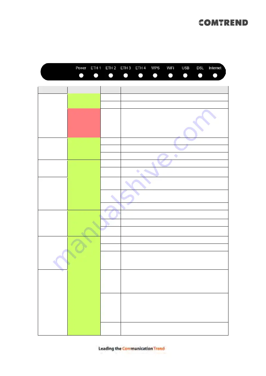
The front panel LED indicators are shown below and explained in the following table.
This information can be used to check the status of the device and its connections.
LED
Color
Mode
Function
POWER
Green
On
The device is powered up.
Off
The device is powered down.
Red
On
POST (Power On Self Test) failure or other
malfunction. A malfunction is any error of
internal sequence or state that will prevent the
device from connecting to the DSLAM or
passing customer data.
ETH 1X-4X
Green
On
An Ethernet Link is established.
Off
An Ethernet Link is not established.
Blink
Data transmitting or receiving over Ethernet.
WPS
Green
On
WPS function is OK.
Off
WPS function is closed or failure.
WiFi
Green
On
The wireless module is ready.
(i.e. installed and enabled).
Off
The wireless module is not ready.
(i.e. either not installed or disabled).
Blink
Data transmitting or receiving over WIFI.
USB
Green
On
USB equipment is connected.
Off
USB equipment is not connected.
Blink
Data transmission.
DSL
Green
On
xDSL Link is established.
Off
Modem power off.
Blink
fast: xDSL Link is training or data
transmitting.
slow: xDSL training failed.
INTERNET
Green
On
IP connected and no traffic detected. If an IP
or PPPoE session is dropped due to an idle
timeout, the light will remain green if an ADSL
connection is still present.
Off
Modem power off, modem in bridged mode or
ADSL connection not present. In addition, if
an IP or PPPoE session is dropped for any
reason, other than an idle timeout, the light is
turned off.
Blink
IP connected and IP Traffic is passing through
the device (either direction)
Summary of Contents for AR-5319
Page 1: ...AR 5319 ADSL2 WLAN Router User Manual 261056 079 Version A1 1 March 6 2017...
Page 40: ...39 4 11 2 Site Survey The graph displays wireless APs found in your neighborhood by channel...
Page 56: ...55 5 3 3 UPnP Select the checkbox provided and click Apply Save to enable UPnP protocol...
Page 67: ...66 Enter the PPP username password given by your service provider for PPP service detection...
Page 111: ...110 Enter the MAC address in the box provided and click Apply Save...
Page 149: ...148 To add a WAN connection go to E2 WAN Connections...
Page 185: ...184 Click Next to continue or click Back to return to the previous step...
Page 203: ...202 STEP 2 Click the Windows start button Then select Control Panel...
Page 204: ...203 STEP 3 Select Devices and Printers STEP 4 Select Add a printer...


