background image

Network Video Recorder 

53 


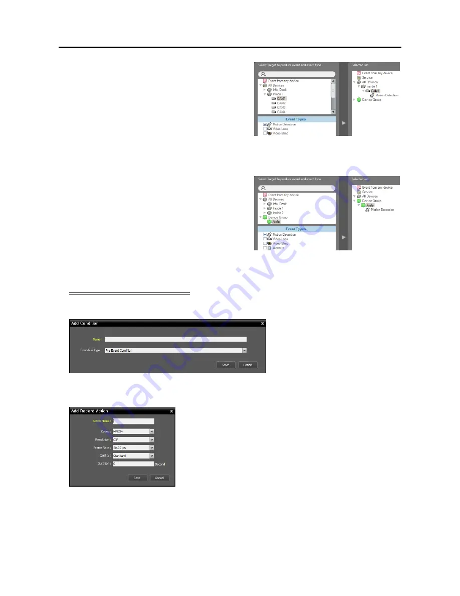
All Devices

: Select to record video when user- 

defined types of events are detected from the selected 
device or camera. 


Click 

All Devices

, and the list of registered devices 

and cameras is displayed 


Under 

All Devices, 

click 

a device or camera to trigger event recording, and 
the list of event types supported by the device or 
camera is displayed in 

Event Types 

below — Select 

the desired event types, and the selected event types 
are added along with the selected device or camera 
to the list under 

All Devices 

on the right. 


Device Group

: Select to record video when the user- 

defined types of events are detected in the selected 
device group. 


Click 

Device Group

, and the list of registered device 

groups is displayed 


Under 

Device Group

, click 

a device group to trigger event recording, and the 
list of event types is displayed in 

Event Types 

below 

— Select the desired event types, and the selected 
event types are added along with the selected device 
group to the list under 

Device Group 

on the right. 


Pre-Event Recording Condition 


The recording service records video prior to event detection when predefined events are detected. 


Enter  the  Preset  name and  select 

Pre 

Event Condition 

from the 

Condition 

Type 

list. 


3.  Set up the recording settings by double clicking the 

Action 

schedule window, and then selecting a desired 

Preset. 


Action Name

: Enter the Preset name. 


Codec, Resolution, Frame Rate, Quality

: The settings are 

only for recording video from network video transmitters.  When 
recording video from other devices, the NVR system performs 
recording based on the settings in each device.  Select the desired 
compression codec, resolution, frame rate and quality.  The frame 
rate cannot exceed l5 ips when video is recorded with the H.264 
codec and 4CIF resolution. 


Duration

: Set up the duration (maximum of 60 seconds) of 

recording when a predefined event is detected.  For Event recording, 
the system records video for the duration from the time an event 
is detected.  For Pre-Event recording, the system records video 
for the duration prior to event detection. 

Summary of Contents for IPNVR016A

Page 1: ...ASED 16 32 CHANNELS ART IPNVR016A IPNVR032A Please read this manual thoroughly before use and keep for future reference Via Don Arrigoni 5 24020 Rovetta S Lorenzo Bergamo http www comelitgroup com e mail export department comelit it ...

Page 2: ......

Page 3: ...RATES USES AND CAN RADIATE RADIO FREQUENCY ENERGY AND IF NOT INSTALLED AND USED IN ACCORDANCE WITH THE INSTRUCTION MANUAL MAY CAUSE HARMFUL INTERFERENCE TO RADIO COMMUNICATIONS OPERATION OF THIS EQUIPMENT IN A RESIDENTIAL AREA IS LIKELY TO CAUSE HARMFUL INTERFERENCE IN WHICH CASE USERS WILL BE REQUIRED TO CORRECT THE INTERFERENCE AT THEIR OWN EXPENSE WARNING CHANGES OR MODIFICATIONS NOT EXPRESSLY ...

Page 4: ......

Page 5: ...Servicing Do not attempt to service this equipment yourself Refer all servicing to qualified service personnel 14 Damage requiring Service Unplug this equipment from the wall outlet and refer servicing to qualified service personnel under the following conditions A When the power supply cord or the plug has been damaged B If liquid is spilled or objects have fallen into the equipment C If the equi...

Page 6: ...tem Overview 15 3 1 Service Manager 15 Menu 15 Status Display 16 3 2 Setup 17 Service 18 Device 19 User 20 Recording Schedule 21 Event Management 22 3 3 Client 22 Menu 23 Site List 25 Panel 25 Menu Preference Settings 26 Chapter 4 Live Video Monitoring 33 4 1 Monitoring Video 33 Layout Monitoring 35 Layout Sequence Monitoring 36 Camera Sequence Monitoring 39 Map Monitoring 40 4 2 Controlling Camer...

Page 7: ...ing Video 68 7 2 Handling Event Recorded Video 69 Chapter 8 System Health Status Monitoring 71 8 1 Health Monitoring 71 8 2 Status Monitoring 72 Chapter 9 Log Search 73 Chapter 10 Device Management 75 10 1 Registering Devices 76 10 2 Managing Devices 78 10 3 Remote Setup of ONVIF Conformance Protocol Devices 81 Chapter 11 User Management 89 Chapter 12 Storage Management 91 Chapter 13 Event Managem...

Page 8: ...nning Services 114 Log In 115 Registering Services 115 Live Video Monitoring 117 Playing Recorded Video 117 16 4 System Overview 118 Service Manager 118 Setup 118 Client 119 Appendix 121 Schedule Setup Examples of Event Recording Mode 121 OSD Information 123 Network Disconnection Log 123 Troubleshooting 124 Specification 127 Index 129 ...

Page 9: ...Network Video Recorder vi ...

Page 10: ......

Page 11: ...vices which do not use the iNEX protocol can be registered up to the maximum number of available recording channels For example if the NVR system is a 16 channel model up to 16 devices that do not use the iNEX protocol can be registered Recording not supported for DVRs Maximum of 16 16 channel model 32 32 channel model channels NOTES In this manual the remote system refers to a network video trans...

Page 12: ...ot be displayed on the monitor when connecting a monitor after turning on the system Refer to Chapter 3 System Overview 3 3 Client Menu Preference Settings Screen Format p 27 for details about the monitor setting Network RJ 45 Connect a Cat5 cable with an RJ 45 jack Refer to Chapter 2 Getting Started 2 2 System Setting p 6 for details about network setting Audio In mic Connect a microphone This is...

Page 13: ... connectors located on the rear panel 1 5 Upgrade You can upgrade the NVR system by using a USB flash drive as follows 1 Connect a USB flash drive containing the upgrade package file to the NVR while the iNEX Client program is running 2 Click iNEX Update under the System Menu in the iNEX Client program The following window appears Click the button and select a Standard conf file The folder path an...

Page 14: ...the iNEX Client program or pressing the power button on the front panel while the system turns on will ask you to confirm turning off the system and the system turns off when you confirm NOTE When connecting a monitor to the D Sub port connect a monitor before turning on the system Video might not be displayed on the monitor when connecting a monitor after turning on the system ...

Page 15: ... ID and password The default user ID is admin and default password is 12345678 You can change the user ID and password in the User menu Refer to Chapter 11 User Management p 89 for details Remember my ID on this computer Check the box if you want to save your ID for logging on Restore last Live sessions Check the box if you want to restore the previous live monitoring sessions in the current Live ...

Page 16: ... 2 2 System Setting Run the Setup program and set up the NVR system Click the System Setup button to display the system setup screen Date Time Date Time Time Zone Displays the date time and time zone of the NVR system ...

Page 17: ... displayed the next time it is connected DVRNS Use DVRNS Allows you to enter the name instead of the IP address of the NVR system by using the DVRNS function when connecting to the NVR system DVRNS Port Enter the IP address domain name and port number of the DVRNS server to register the NVR system Use NAT Check the box when the NVR system uses a NAT Network Address Translation device for network c...

Page 18: ... administration service and add the devices to a device group in order to perform any operation Run the iNEX Setup program 1 Select the Device menu 2 Click All Devices in the Site panel and then the button at the bottom of the Site List panel The Device Scan window appears ...

Page 19: ...ame Allows you to enter the device s domain name registered on a DNS server if the device uses the Domain Name Service Select the devices to register by checking the box beside each device name in the list Selecting the Select All box selects all devices in the list NOTES Depending on the model the device may not be supported even though the iNEX program supports the device s protocol Ask your dea...

Page 20: ... recording service on a Device Setup tab while setting up the recording service in the Service menu Refer to Chapter 12 Storage Management p 91 for details Apply to All Devices Select to apply the same user ID and password to all selected devices if you selected more than one device and the selected devises have the same user ID and password NOTES If the device is a DVR it might be necessary to en...

Page 21: ...ton at the bottom of the Site List panel displays the Edit Device Group window and allows you to edit the selected device group Refer to Chapter 10 Device Management p 75 for details 2 4 Live Video Monitoring 1 Check that the devices were added to a device group in the Site list 2 Click the Live tab on the tab panel Select a site to connect to from the Site list and drag and drop it on the Live sc...

Page 22: ...et 2 Double click anywhere in the empty space of each schedule window and the Preset setup window appears 3 Select a desired Preset from the Preset list or click the button to add a new Preset Selecting a Preset from the list and clicking the or button deletes the selected Preset or allows you to edit the selected Preset settings Clicking the OK button applies the settings ...

Page 23: ...l Select a site to connect to from the Site list and then drag and drop it on the Play or DVR Search screen Recorded video from the selected site is displayed on the screen You can search and play back recorded video by using the panel toolbar and timetable at the bottom of the Play or DVR Search panel Refer to Chapter 6 Recorded Video Playback Exportation p 57 for details ...

Page 24: ...User s Manual 14 ...

Page 25: ...R system Refer to Chapter 2 Getting Started 2 1 Connecting Login p 5 for details about the login Go to the System Menu Click iNEX Service Manager Run the iNEX Service Manager program Menu Allows you to control the operation of the services or display the system log Status Display Displays the status of services Menu Option Server Option You can change the Watchdog setting Timeout Min Set up the wa...

Page 26: ...rch the system log Setting up the time range of the log and clicking the Search button displays the log information Selecting First displays from the oldest log entries regardless of date Selecting Last displays to the newest log entries regardless of date Status Display Service Displays the list of services supported by the NVR system Administration Service Manages information of services devices...

Page 27: ...for details Device Allows you to register and manage sites Refer to Device p 19 for details User Allows you to register and manage users or user groups Refer to User p 20 for details Recording Schedule Allows you to set up recording schedules Refer to Recording Schedule p 21 for details Event Management Allows you to set up event management schedules Refer to Event Management p 22 for details Syst...

Page 28: ... the IP address and port number Status Displays the connection status Incremental Search Allows you to search for a service registered in the NVR system Entering text that you want to search for causes the search results to be displayed Search results are displayed immediately as matching text is found As you enter more text the results narrow Add Remove Edit Allow you to add remove and edit a ser...

Page 29: ...to record Incremental Search Allows you to search for a device or site registered in each group Selecting a group in the Site panel and entering text that you want to search for causes the search results to be displayed Search results are displayed immediately as matching text is found within the selected group As you enter more text the results narrow Add Remove Edit Allow you to add remove and e...

Page 30: ...ity settings cannot be edited User List Panel Displays the list and information about users registered in each group Incremental Search Allows you to search for a user registered in each group Selecting a group in the Group Panel and entering text that you want to search for causes the search results to be displayed Search results are displayed immediately as matching text is found within the sele...

Page 31: ... Based Recording or to set up recording settings for Instant Recording Refer to Chapter 5 Recording 5 1 Setting up Recording Schedule p 47 for details Schedule Table Displays the current recording schedule by day or week Clicking the button displays the today s recording table Clicking the button displays a calendar Incremental Search Allows you to search for a registered schedule Entering text th...

Page 32: ...edule by day or week Clicking the button displays the today s event management table Clicking the button displays a calendar Incremental Search Allows you to search for a registered schedule Entering text that you want to search for causes the search results to be displayed Search results are displayed immediately as matching text is found within the registered schedule As you enter more text the ...

Page 33: ...pter 13 Event Management 13 2 Managing Events Live Popup p 99 for details about the live popup screen Panel Toolbar Timetable Displays the toolbar or timetable depending on the panel Refer to Chapter 4 Live Video Monitoring p 33 or Chapter 6 Recorded Video Playback Exportation p 57 for details Panel Allows you to select which panel to use Refer to Panel p 25 for details Menu System New Tab Adds pa...

Page 34: ...Live Video Monitoring 4 1 Monitoring Video Event Spot Setup p 34 for details Set Map Event Spot Sets up a selected camera screen as a map event spot screen Refer to Chapter 4 Live Video Monitoring 4 1 Monitoring Video Map Event Spot Setup p 35 for details Layout Sequence Starts or stops the layout sequence Refer to Chapter 4 Live Video Monitoring 4 1 Monitoring Video Layout Sequence Monitoring p 3...

Page 35: ...r playback Refer to Chapter 4 Live Video Monitoring 4 1 Monitoring Video p 33 or Chapter 6 Recorded Video Playback Exportation 6 1 Playing back Recorded Video p 57 for details Layout Sequence Displays the list of registered layout sequences Clicking a layout sequence in the list and dragging and dropping it on the screen starts layout sequence monitoring Refer to Chapter 4 Live Video Monitoring 4 ...

Page 36: ...hapter 8 System Health Status Monitoring p 71 for details Status Displays the status of a desired device in real time supported only for devices which use the iNEX protocol Refer to Chapter 8 System Health Status Monitoring p 71 for details NOTE You can change the panel name by clicking the right mouse button on each panel tab Adding Deleting Panel Floating Docking Panel Go to the System menu Clic...

Page 37: ...ty slide bar allows you to adjust the opacity of OSD On Screen Display OSD Magnification changes the OSD size depending on the screen size See below about OSD information Camera Title Displays the camera name set in the iNEX program Title Bar Separates the title display area from an image display area at the top Status Icon Displays status OSD Red During Time Lapse or Event Based recording Orange ...

Page 38: ...color space standard to display video on the screen The color quality or display performance of video might be affected depending on the color space standard selected Deinterlacing Enhances image display quality of interlaced video on the screen by eliminating horizontal scan lines or noise in areas with motion Select the desired deinterlace filter Anti Aliasing Enhances image display quality of v...

Page 39: ...event detection The event list will remain on the Instant Event List even if the time has expired if the event list has 100 or fewer items Column Select the information to be displayed in Instant Event List Callback Port Set up the port number to receive a callback message from the device This setting will be used only when the monitoring service does not run The NVR system uses the callback port ...

Page 40: ...he RIP protocol Ihe higher the number is the less the video stutter Ihe lower the number is the higher the real time monitoring Map Activate Auto Focusing Enlarges the area where the event detected device is placed when an event is detected Focusing Event Select a desired event for auto focusing Focusing Duration Set up the duration for auto focusing to last Focusing Minimum Dwell Set up the durat...

Page 41: ...onto Windows This is supported in the Client system Auto login at startup The Client program automatically logs in with the login information from the previous connection when it starts Checking the Restore last Live sessions at auto login box restores the previous live monitoring sessions in the current Live panels 3l ...

Page 42: ...User s Manual 32 ...

Page 43: ...e list and drag and drop it on the Live screen Live video from each camera is displayed on the screen You can move a camera screen to the desired location on the Live screen without disconnecting the current connection while monitoring video Select a camera screen and drag and drop it on the desired location NOTE The system performance might seriously deteriorate when simultaneously monitoring or ...

Page 44: ... screen on the current monitoring screen 2 Click the Hotspot button on the toolbar at the bottom of the Live panel and the current connection in the selected camera screen is released The hotspot screen is surrounded by a red outline 3 Select any camera on the screen Video from the selected camera is displayed on the hotspot screen and you can control the camera Event Spot Setup NOTE The event spo...

Page 45: ...detected is displayed on the map event spot screen Map CAM3 An event is detected Layout Monitoring You can monitor video from multiple cameras in a predefined layout A layout should be registered on the NVR system for layout monitoring Refer to the following explanation for details about layout registration NOTE A layout in this manual refers to a screen organization created by arranging specific ...

Page 46: ...amera assigned to the camera screen from the layout screen Hotspot Selecting a camera screen in the layout screen and clicking this button sets up the camera screen as a hotspot screen Event Spot Selecting a camera screen in the layout screen and clicking the button sets up the camera screen as an event spot screen Map Event Spot Selecting a camera screen in the layout screen and clicking the butt...

Page 47: ...s the layout sequence Example Layout 1 Layout 2 Layout Sequence Registering Layout Sequences 1 Go to the System menu and click iNEX Setup and select the Device menu 2 Click Layout Sequence in the Site panel and then the button at the bottom of the Site List panel on the right The Add Layout Sequence window appears 3 If no layout to be sequenced is registered click the Add Layout button The Add Lay...

Page 48: ...want to search for causes the search results to be displayed Search results are displayed immediately as matching text is found As you enter more text the results narrow Selected Layout Sequence List Displays the list of layouts registered for the layout sequence Duration sec displays the duration for each layout to be displayed on the screen Clicking the Apply all button applies the duration sett...

Page 49: ...Sequence list and drag and drop it on the Live screen Video from cameras added to the camera sequence is displayed on the screen sequentially 2 Clicking the Camera Sequence button on the camera screen control toolbar stops or starts the camera sequence Example Camera 1 Camera 2 Camera Sequence Registering Camera Sequences 1 Go to the System menu and click iNEX Setup and select the Device menu 2 Cl...

Page 50: ...l button applies the duration setting to all cameras in the list Select a camera from Device List click the button and the selected camera is added to Selected Camera Sequence List Clicking the OK button completes registration of the camera sequence Map Monitoring You can monitor video from cameras event detection and input output device status on a map for devices registered on the NVR system A m...

Page 51: ...ed in unique colors if you have set up status color during the map setup When more than one event or status is detected at the same time the color reflecting each event detection or status is displayed sequentially 4 2 Controlling Cameras A control toolbar and a screen menu are provided for controlling camera Control Toolbar When selecting a camera screen and hovering the mouse cursor over the cam...

Page 52: ...am if the device is in the multistream mode for live monitoring supported only for devices which use the iNEX protocol Hotspot Sets up a selected camera screen as a hotspot screen Refer to Hotspot Setup p 34 for details Event Spot Sets up a selected camera screen as an event spot screen Refer to Event Spot Setup p 34 for details Map Event Spot Sets up a selected camera screen as a map event spot s...

Page 53: ...ol p 43 for an explanation of this function Advanced Menu Displays the Advanced Menu window and allows you to use more features that the PTZ camera supports Refer to the PTZ camera manufacturer s manual for details about additional features Close Exits the PTZ mode and returns to the control toolbar PTZ Preset Control You can save camera directions as a Presets so that you can move the camera dire...

Page 54: ... for the button Previous Map Next Map Moves to the previous or next connected map of the maps that have been connected to the current map screen Maps can be connected by using map link or by selecting a map from the map list and dragging and dropping it on the current map screen Auto Focusing Enlarges the area where the event detected device is placed when any event is detected When events are det...

Page 55: ...us Next Auto Focusing Actual Size xl Zoom Finder Zoom In These function the same as clicking the individual buttons on the control toolbar Refer to Control Toolbar p 44 for details List Displays the list of the previous or next connected maps Selecting a map from the list moves to the selected map Reload Reloads the connection of the current map Focusing Event Focusing Duration Allows you to set u...

Page 56: ...User s Manual 46 ...

Page 57: ...ng service of iNEX system only the first NVR system or recording server that is connected to the device records video Once a NVR system or a recording service connects to the device other NVR systems or recording servers will not record video from the device unless the connection of the first NVR system or recording service is released The iNEX program performs recording with the settings of codec...

Page 58: ... than one time range The higher the schedule position is in the Schedule Setup window the higher its priority is Condition Sets up the recording type You can set up more than one recording type for the same recording period The higher the schedule position is in the Schedule Setup window the higher its priority is Action Sets up the recording settings network video transmitters only You can set up...

Page 59: ... a desired Preset You can add a new Preset or edit a saved Preset by clicking the Add or Modify button Refer to the following explanation for setting up a schedule Name Enter the Preset name Color Click the button and select a desired color The scheduled time section will be highlighted with the selected color in the schedule table Period Set up the schedule time Selecting the Infinite option caus...

Page 60: ...n Clicking the Add or Modify button displays the following setup screen Action Name Enter the Preset name Codec Resolution Frame Rate Quality The settings are only for recording video from network video transmitters When recording video from other devices the NVR system performs recording based on the settings in each device Select the desired compression codec resolution frame rate and quality Th...

Page 61: ...le Ready to record The Time Lapse Recording or Event Based Recording OSD is displayed in the upper right corner of the camera screen of the Live screen in the iNEX Client program Setting up Event Based Recording During Event or Pre Event recording the recording service records video based on the event detection for the scheduled time supported only for devices which use the iNEX protocol and regis...

Page 62: ...vent Recording Condition The recording service records when predefined events are detected Name Enter the Preset name Condition Type Select Event Condition Select Target to produce event and event type Select event types that trigger video recording Event from any device Select to record video when user defined types of events are detected Click Event from any device and the list of event types is...

Page 63: ... added along with the selected device group to the list under Device Group on the right Pre Event Recording Condition The recording service records video prior to event detection when predefined events are detected Enter the Preset name and select Pre Event Condition from the Condition Type list 3 Set up the recording settings by double clicking the Action schedule window and then selecting a desi...

Page 64: ...ng status in the Device menu Click All Devices in the Site panel and all registered devices are displayed in the Site List panel Click the arrow button beside the device name and check the status Record During Time Lapse recording or Event Based recording Instant Recording During Instant recording Idle Ready to record Not Use Camera disabled Video Loss On video loss The Time Lapse Recording or Eve...

Page 65: ...on schedule window allows you to add a new schedule with the same time range and target Deleting a Schedule Clicking the button in the upper right corner of any schedule window deletes the schedule Changing Schedule Priority Clicking the or button in the upper left corner of each schedule window changes the priority of the schedules The higher the schedule position is in the Schedule Setup window ...

Page 66: ...he settings in each device Select the desired compression codec resolution frame rate and quality of video The frame rate cannot exceed l5 ips when video is recorded with the H 264 codec and 4CIF resolution 3 Run the iNEX Client program Select a camera screen on the Live screen on which video to record is displayed and click the Instant Recording button on the control toolbar The Instant Recording...

Page 67: ...the tab panel Select a camera device or device group from the Site list and drag and drop it on the Play or DVR Search screen Recorded video from each camera is displayed on the screen You can move a camera screen to the desired location on the Play or DVR Search screen without stopping the current playback while playing back video Select a camera screen and drag and drop it on the desired locatio...

Page 68: ...ideo segment when the DVR s time and date have been reset to a time that is earlier than previously recorded video and there is more than one video segment in the same time range due to time overlap supported only for DVRs which provide the hour segments timetable Data Source Selects the data source to be searched supported only for the DVR Search panel Search on Local Searches recorded data on pr...

Page 69: ...ng information for all cameras Clicking the button displays the recording information for the selected camera on the screen NOTE The timetable will differ depending on the model of the device Current Playback Date Time Indicates the video time for the current playback location on the timetable Recorded Period Displays the date and time period of the recorded data Clicking anywhere in the empty spa...

Page 70: ...nt from the list displays the event detected image on the screen Clicking the button in the top right corner of the event list displays next results Control Toolbar The control toolbar is displayed over a selected camera screen when hovering the mouse cursor over the camera screen Hovering the mouse cursor over each button displays a tooltip for the button Object Motion Search Allows you to search...

Page 71: ...ot on Motion Event button on the panel toolbar displays snapshots of images recorded during the event based recording event and pre event in the Play panel The timetable displays the recording information of the selected snapshot Clicking anywhere on the recorded data in the timetable displays a snapshot of the selected time Use Popup Viewer Enables display of the popup viewer screen Hovering the ...

Page 72: ...ge Zoom Control Clicking the Zoom button on the control toolbar allows you to zoom on the current video NOTE PIP is an abbreviation of Picture in Picture and indicates the smaller screen within a screen Dragging the mouse on the camera screen moves the zoomed in area Slide Bar Adjusts the enlargement ratio You can adjust the enlargement ratio also by using the mouse scroll wheel Actual Size Zoom E...

Page 73: ... as an AVI File p 65 for details Exporting as a Self Player File The recorded video is exported as a self player file exe From To Enter the date and time of video to export Selecting First sets the date and time to the date and time of the first available recorded video Selecting Last sets the date and time to the date and time of the last available recorded video Clicking the l Minute 3 Minute lO...

Page 74: ... key which will display DirectX Diagnostic Tool dialog box Then move to the Display tab and make sure DirectDraw Acceleration is set to Enabled Test DirectDraw by selecting the DirectDraw Test button when using the Microsoft Windows XP operating system Please check the driver version of the video card and update it to the latest version available If you still have display problems after changing a...

Page 75: ...iasing Screen Enhances image display quality on the screen by smoothing stair stepping aliasing effects in the enlarged image If video plays slow because of your CPU s slow speed releasing the Anti Aliasing Screen option might improve playback speed Saves the current images Save as Image Saves the current image as a bitmap or JPEG file Save as Image Actual Size Saves the current image as a bitmap ...

Page 76: ... Selecting this option enables the Quality setting below Size Set up the file size for compressing the file Original Ratio Saves images with fitting within the screen size while maintaining their original ratio Fit to Screen Saves images with fitting to the screen size regardless of the aspect ratio regardless of the aspect ratio Fit to Screen Aspect Ratio Saves images with fitting to the screen s...

Page 77: ...for details The event detection functions of the device should be enabled 7 1 Handling a Monitoring Event You can monitor live video from a camera where an event is detected or play back event recorded video if video of the selected event has been recorded Fan Error On Off The event list displays live and callback events from the registered devices The callback events are listed only when the remo...

Page 78: ...ected event occurred is displayed on the screen Playing Video Playing event recorded video is supported in the Play panel If the Play tab is not on the tab panel go to the System menu click New Tab and Play Click the Play tab on the tab panel Select a desired event from the event list and drag and drop it on the Play screen The event recorded video is displayed on the screen ...

Page 79: ...to sort data as you want 2 Double click the desired event in the Event panel the Play panel is displayed and the event video is displayed on the Play screen Clicking the right mouse button allows you to select a desired Play panel If other cameras were associated with the Event Recording recorded video from the associated cameras is displayed together on the screen Event Toolbar The toolbar at the...

Page 80: ... event type to search Search Starts searching events based on search conditions Export Exports the resulting event search list as a text file txt or CSV file csv Print Prints the resulting event search list More Displays more results 70 ...

Page 81: ... health monitoring status of devices for all device groups in summary Total Displays the number of devices in all device groups Problem Displays the number of devices where a problem is detected Unreachable Displays the number of devices that are not connected Healthy Displays the number of devices where no problem is detected Detailed List Displays the status of each device in detail Status Displ...

Page 82: ... the system version information Event Displays the status of event detection When an event is detected the icon is displayed in corresponding color Hovering the mouse cursor over an icon displays the event type in a tooltip Alarm Out Displays status of the alarm out signals System Check Displays the function status of the device and recording Function Buttons Disconnect Disconnects the current con...

Page 83: ... to sort data as you want Select a log type to search from the drop down list User Log Displays log entries from the iNEX Client program Health Log Displays log entries of the system health monitoring for the registered devices Admin Service Log Displays log entries from the administration service Recording Service Log Displays log entries for recording service Monitoring Service Log Displays log ...

Page 84: ...or Last Clicking the l Hour 6 Hour Today 3 Day or l Week button adjusts the time interval between From and To Selecting First or Last searches log entries from the first or to the last Condition Selects a log type to search Search Starts searching log entries based on search conditions Export Exports the searched log entries as a text file txt or a CSV file csv Print Prints the searched log entrie...

Page 85: ...l0 l Registering Devices p 76 for details about registering device groups Layout Displays the registered layouts You can monitor video from multiple cameras in a predefined layout Refer to Chapter 4 Live Video Monitoring 4 l Monitoring Video Layout Monitoring p 35 for details Layout Sequence Displays the registered layout sequences You can monitor video from multiple cameras sequentially in more t...

Page 86: ... the device Auto Scan LAN Lists devices in a LAN environment supported only for the network video devices If the device uses the ONVIF Conformance protocol this function is supported only when you have checked the Disable WS Discovery Windows Service fdPHost FDResPub box during the software installation in Microsoft Windows Vista or later operating systems IP Address Allows you to enter the IP add...

Page 87: ...ng service performs recording according to a recording schedule The channel number of the recording service indicates the maximum number of cameras that can be registered and the name indicates the name of a recording service which was set during the Service menu setup When selecting the Do not record option the iNEX program treats the device during the Schedule setup as though it was not register...

Page 88: ...ered group displays the list of devices added to the device group and connection status in the Site List panel If the connection was not made properly the network disconnection log is displayed Refer to Appendix Network Disconnection Log p l27 for details about the network disconnection log Selecting the registered device group and then the button at the bottom of the Site panel displays the Edit ...

Page 89: ...P address The device name you enter should match the name set when DVRNS was set up in the device Port Edit the port numbers The port numbers you enter should match the port numbers set in the device for remote connection Admin remote monitoring Watch recording Record and two way audio communication Audio ID Password Edit the user ID and password for connection to the device Connection Test Click ...

Page 90: ... displays the following screen supported only for devices which use the iNEX protocol Checking Device Status Click the button at the top right corner and select an upgrade file If the device is a PC based DVR check the PC Based DVR box and click the button The list of available devices is displayed Selecting Show all devices displays all registered devices Select devices and click the Upgrade butt...

Page 91: ...pported only for an alarm in or audio in device Video from the selected camera channel will be displayed on the event spot screen when an alarm in or audio in event is detected 10 3 Remote Setup of ONVIF Conformance Protocol Devices If the device uses the ONVIF Conformance protocol the iNEX program displays live video or records video with the settings set during the device remote setup in the iNE...

Page 92: ... setup is closed when the system restarts Reset Returns all the settings of the system to the original factory settings Except Network Information Returns all the settings except network settings to the original factory settings Include Network Information Returns all the settings including network settings to the original factory settings The iNEX remote setup is closed when the network settings ...

Page 93: ...cking the Apply button applies the change and the changed information is displayed the next time it is connected This may not be supported when the device s IP address is set to Set Manually DDNS Update Type Updates the device s IP address information in the NVR system automatically when the device s IP address is changed No Update Does not update the device s IP address information automatically ...

Page 94: ...e iNEX Setup program too Refer to 10 2 Managing Devices Editing Device Information p 79 for details Scope Parameters Click the button and add the scope parameters of WS Discovery Web Services Discovery protocol if necessary Discovery Mode Sets whether or not to permit discovery of the device When Non Discoverable is selected the Auto Scan function is not supported for the devices which use the ONV...

Page 95: ...figuration Clicking the See More button allows you to check the details of the selected audio encoder configuration Refer to Audio p 86 for details about the audio encoder configuration PTZ Select a PTZ setting When None is selected PTZ control of the device will not be supported Video Frame Rate Limit Select a maximum frame rate Source Configuration Displays the source configuration information C...

Page 96: ...te Sample Rate Select the sampling rate The higher the value is the better the sound quality and the larger the data size I O Mode Set the relay mode for the input and output devices Monostable After setting the idle state the relay returns to its idle state once the delay time expires Bistable After setting the idle state the relay remains in this state Delay Time Set the delay time until the rel...

Page 97: ...o zoom in a certain position If the position cannot be zoomed the operation fails Relative Pan Tilt Translation Select the movement setting to move in a certain direction based on the current position Relative Zoom Translation Select the zoom setting to zoom in in a certain direction based on the current position Continuous Pan Tilt Velocity Select the movement setting to move continuously in a ce...

Page 98: ...User s Manual 88 ...

Page 99: ...uthoritylevels for each function of the iNEX program The Administrators group has authority for all functions and the authority settings are not editable Run the iNEX Setup program Select the User menu l Click the button at the bottom of the user group list The Add User Group window appears ...

Page 100: ...ification of events when events occur Clicking the Modify button allows you to edit the users Refer to Chapter l3 Event Management l3 2 Managing Events Event Acknowledgement p l00 for details about the event forwarding E Mail Enter the email address of the user if you want to notify event detection to the user via E mail An email address must include the character to be a valid address Refer to Ch...

Page 101: ...em or recording server The total amount of storage for one NVR system cannot exceed 50 000 GB The C drive is not used as storage The NVR system automatically allocates storage for recording to all hard disk drives except the C drive when system boots l Select a recording service and click the button at the bottom The Setup Recording Service window appears Select the Device Setup tab The list of ca...

Page 102: ... Recorded Timetable When the network connection between the NVR system and the devices is too slow or a hard disk drive in the NVR system is damaged the recorded data and the timetable information of the recorded data might not match and the timetable in the Client program might display incorrect information In this situation clicking the button reconstructs the timetable to display recorded data ...

Page 103: ... the iNEX protocol 13 1 Setting up Event Management Schedule First check the following Devices should be added to a device group Refer to Chapter l0 Device Management p 75 for details Run the iNEX Setup program Select the Event Management menu and set up the event management schedule following the procedures below Click the Schedule Setup button at the bottom The Schedule Setup window appears and ...

Page 104: ...mail Setup Sets up the SMTP server information for sending email This only works when the action type is set to Email Notification during the Action Preset setup NOTE In the schedule setup Preset indicates a single setting in which the setting values of Time Coverage Condition or Action are saved l Set up the schedule time by double clicking the Time Coverage schedule window and then selecting a d...

Page 105: ...tings without limiting the period Repeat Repeat Period Set up the interval and interval period Events will be notified to the preset users at the designated interval during the interval period 2 Set the event condition by double clicking the Condition schedule window and selecting a desired Preset of event condition You can add a new Preset or edit a saved Preset by clicking the Add or Modify butt...

Page 106: ...evice group Click Device Group and the list of registered device groups is displayed Under Device Group click a device group to trigger event notification and the list of event types is displayed in Event Types below Select the desired event types and the selected event types are added along with the selected device group to the list under Device Group on the right 3 Set up the event action by dou...

Page 107: ...nter the duration for the display of popup video to last Select popup Cameras Select the cameras maximum 4 from which video will pop up Selecting the Same cameras that triggered an event option pops up video only from the camera where an event is detected not supported for alarm in events and audio detection events Event Acknowledge Select to display an event log in the iNEX Client program when an...

Page 108: ...lows you to add a new schedule with the same time coverage Adding a new schedule with the same time range and target Clicking the button in the upper left corner of the Action schedule window allows you to add a new schedule with the same time range and target Deleting a Schedule Clicking the button in the upper right corner of any schedule window deletes the schedule Changing Schedule Position Cl...

Page 109: ...control toolbar allows you to control the camera Hovering the mouse cursor over a button displays a tooltip for the button Refer to Chapter 4 Live Video Monitoring 4 2 Controlling Cameras Control Toolbar p 4l for details about the toolbar buttons When clicking the right mouse button on the popup screen a popup screen menu is displayed The screen menu allows you to control the camera Layout Select ...

Page 110: ...d of an event New Events Displays events that the Client system is notified of but not yet acknowledged Acknowledge Event Acknowledges the selected event in the list and the selected event is moved to the Acknowledged Events list Event Forwarding Forwards the event to all users or the users defined in the Monitoring Group setting during the User setup Only users currently connected to the Client s...

Page 111: ... or Last Clicking the l Hour 6 Hour Today 3 Day or l Week button adjusts the time interval between From and To Selecting First or Last searches log entries from the first one or to the last one Condition Selects a log type to search Search Starts searching log entries based on the search conditions Load Preset Applies the column sorting saved in the current system Save Preset Saves the current col...

Page 112: ...User s Manual l2 ...

Page 113: ... protocol 14 1 Registering Map l Run the iNEX Setup program Select the Device menu 2 Click Map in the Site panel and then the button at the bottom of the Site List panel on the right The Map Editor window appears 3 Select an input output device connected to a device or a sub map in the Site panel and drag and drop it on the canvas 4 Set up the map Refer to l4 2 Setting up Map p l04 for details 5 E...

Page 114: ...ings in the device Background Image Inserts a background image on a canvas Status Color Sets up a unique color for each event detection or status of input output devices Delete Selecting an input output device icon or a map link on the canvas and clicking this button deletes the icon or link from the canvas Property Sets up the property of the canvas input output device icons or map links Event Ac...

Page 115: ...utloutput device icon Name Sets the name of the device icon Icon Ratio Sets the image and ratio of the device icon X CoordinatelY Coordinate WidthlHeight Sets the position and size of the device icon You can also sets the position and size by using the mouse drag and drop on the canvas Associated Camera Associates the device with a camera supported only for an alarm in or audio in device You can m...

Page 116: ... select a value from the drop down list Click Sets the Instant Viewer window to be displayed when clicking the inputloutput device icon on the map When clicking an alarm in icon clicking activates or deactivates alarm out Motion Detection Object Detection Video Loss Video Blind Alarm In etc Sets video from a camera to pop up or be displayed on the event spot screen when an event is detected ...

Page 117: ...024x768 24bpp or higher Hard Disk Drive 350 MB or more free space LAN Gigabit Ethernet or faster Minimum System Requirements Operating System Microsoft Windows XP Home SP 3 CPU Intel Pentium IV 3 0 GHz or faster RAM l 5 GB or more VGA ATI RadeonTM HD 2400 or NVIDIA GeForce FX5500 ATI recommended l024x768 24bpp or higher Hard Disk Drive 350 MB or more free space LAN l0ll00 Mbps Ethernet or faster 1...

Page 118: ...elect Client and click Next 5 Designate the folder path to install the Client program Clicking the Disk Cost button shows the available and required disk space for each hard disk drive for the installation Then click Next 6 When the following screens appear click Next ...

Page 119: ...ck OK NOTES To properly display the selected language your PC s operating system should be set to support the selected language To change the iNEX program s language after the software has been installed select Language Selector in the iNEX Utility folder of the Start menu before running the iNEX program NOTE The following Utility programs are provided Go to the Start Menu Click iNEX and then Util...

Page 120: ...een appears 4 Click the Remove All or Do not remove button when the following screen appears Clicking the Remove All button deletes all saved data including recorded video and previous settings in the system Clicking the Do not remove button uninstalls the software without deleting any saved data in the system and keeps all saved data in the system NOTE The deleted data cannot be restored once the...

Page 121: ...r or server system refers to a PC running the federation service 16 1 Installation NOTES You cannot install the federation service on a PC on which any other iNEX services are installed In the Windows Start menu go to Control Panel Double click the Power Options to open the Management Properties dialog box Under the Power Schemes tab set both Turn off monitor and Turn off hard disks to Never CAUTI...

Page 122: ...drive for the installation Then click Next 6 When the following screen appears click Next NOTE The following screen appears when using Microsoft Windows Vista or later operating systems It is recommended that you check the Disable WS Discovery Windows Service fdPHost FDResPub box If you do not check the box the iNEX program cannot auto scan devices using ONVIF protocol when scanning devices for de...

Page 123: ... program s language after the software has been installed select Language Selector in the iNEX Utility folder of the Start menu before running the iNEX program NOTE The following programs are provided apart from the iNEX program running Go to the Start Menu Click iNEX and then Utility ProblemReport SecretKey You will use it following the directions of your dealer or distributor when your dealer or...

Page 124: ...out deleting any saved data in the system and keeps all saved data in the system NOTE The deleted data cannot be restored once the data is deleted 5 Click the OK button to complete the uninstall process 16 3 Getting Started Running Services When the federation service installed the service runs automatically You can also start or stop running the service manually Go to the Start Menu in the federa...

Page 125: ... Address Service Port Designate the name of the federation service and enter the IP address and port number of the federation server default ll000 User ID Password Enter your user ID and password The default user ID is admin and default password is l2345678 You can change the user ID and password in the User menu Refer to Chapter ll User Management p 89 for details Remember my ID on this computer ...

Page 126: ... NVR system administration service Address Port Enter the IP address and port number of the NVR system ID Password Enter the ID and password for connection to the NVR system Only the users in the Administrators group are allowed to connect to the NVR system from the federation service Connection Test Click the button to test the connection to the NVR system with the information entered above ...

Page 127: ...n the tab panel Select a site to connect to from the Site list and drag and drop it on the Live screen Live video from the selected site is displayed on the screen Monitoring video in the Client program of the federation server is identical to monitoring of the NVR system administration service Refer to Chapter 4 Live Video Monitoring p 33 for details Playing Recorded Video ...

Page 128: ...ists of the Service Manager Setup and Client programs Setting up and operating each program of the iNEX Federation program is identical to that of the NVR system except for the following functions The following functions are not supported by the iNEX Federation software Client program Live and callback event notification map monitoring instant recording Event Manager panel Event History tab Health...

Page 129: ...pported only for devices which use the iNEX protocol Panel ToolbarlTimetable Displays the toolbar or timetable depending on the panel Panel Allows you to select which panel to use Site List Displays the list of registered sites that are registered on the administration or federation service Federation Service Displays the list of NVR systems administration services registered on the federation ser...

Page 130: ...ence in the list and dragging and dropping it on the screen starts layout sequence monitoring Camera Sequence Displays the list of registered camera sequences registered on the federation service Clicking a camera sequence in the list and dragging and dropping it in the desired location on the screen starts camera sequence monitoring l20 ...

Page 131: ...nt Recording Mode NOTE Event recording is supported only for network video devices which use the iNEX protocol Example I If motion detection events are detected at camera l on the Inside l device and you want to record video from that camera set up as follows l2l ...

Page 132: ...l Devices Inside 1 and CAM1 in order Event Types Select Motion Detection Action preset Select a desired recording setting Target preset Select the Same cameras that triggered an event option Example II If motion detection events are detected at camera l on the Inside 1 device and you want to record video from that camera and camera l of the Inside 2 device set up as follows ...

Page 133: ...the screen Camera Sequence Indicates the cameras are being sequenced upper right corner of the screen Red Is displayed during recording in Time Lapse Recording or Event Based Recording mode Orange Is displayed during recording in Instant Recording mode Indicates video is being recorded in the NVR system upper right corner of the screen Zoom In Indicates video is zoomed in upper right corner of the...

Page 134: ...t is connected to the device records video Once a NVR system or a recording service connects to the device other NVR systems or recording servers will not record video from the device unless connection of the first NVR system or recording service is released To record video in the current NVR system delete the device registration or disable the device in the other NVR system or iNEX system by edit...

Page 135: ...Recorder 125 Problem Possible Solution A logo appears and then freezes or sometimes the screen is black There is a problem with the Main Board Reboot the NVR system If it happens often ask your dealer or distributor ...

Page 136: ...User s Manual 126 ...

Page 137: ...imary Storage SATA hard disk drive Expandable up to 4 GENERAL Dimensions W x H x D l6 9 x 3 5 x l5 7 430mm x 88mm x 400mm Unit Weight l8 63 lbs 8 45kg Shipping Weight 26 l2 lbs ll 85kg Shipping Dimensions W x H x D 2l 3 x ll x 23 2 540mm x 280mm x 590mm Operating Temperature 4l F to l04 F 5 C to 40 C Operating Humidity 0 to 90 Power AC l00 240V 50l60 Hz 3 0 l 5A Approvals FCC CB CE ULii i The netw...

Page 138: ...User s Manual 128 ...

Page 139: ......

Page 140: ...User s Manual Via Don Arrigoni 5 24020 Rovetta S Lorenzo Bergamo http www comelitgroup com e mail export department comelit it V1 6 129 ...

Reviews: