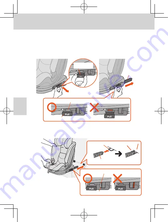
②
③
Color indicator A (green)
Connector adjustment lever
ISOFIX connector
①
②
Connector release button
Color indicator B (green: locked)
ISOFIX connector
①
ISOFIX anchor
Click
5
6
①
Fit the ISOFIX connectors onto the left and right ISOFIX anchors
and push until they lock with a “click” sound.
②
Check that the color indicator B shows the locked condition
(“green” is visible).
①
While pulling the connector adjustment lever on the side of the main
body,
②
Pull out the ISOFIX connectors as far as possible.
③
Release the connector adjustment lever and check that the color
indicator A is “green”.
※
Perform this procedure for both the left and right connectors.
39
Installing to the vehicle
Using in Group 2 and Group 3 mode
Connector
adjustment lever


