Page 24
INSTALLATION & USER'S MANUAL CLITE2
Operator panel connections
9.6
The operator panel is designed to be immersed into the bridge panel, for dimensions, see
drawing in section
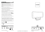
The following connections are available on the back of the panel:
1. Power supply 9-28 VDC via local power supply on the boat or 24VDC via terminals in
the E-box. One of the benefits of supplying power to the panel from the box is that the
panel will be de-energized together with the e-box via the main switch.
2. Ethernet connection directly to the electrical cabinet or Ethernet switch via RJ45
connector.
Shielded Keystone Modular Feed through Coupler, RJ45-RJ45 included.
3. Earth connection to the panel, this is needed to suppress electrical disturbances and
prevent ESD discharge damaging.
Electrical protection:
The panel is protected against wrong polarity and over-current protected by an internal, type:
T1A (Slow-Blow glass fuse 5x20mm).
Wire#1
0v (-)
Wire#2
24Vdc (+)
Earth-
wire
RJ45
Connector
Ethernet Cable
Power Cable
Gore protective
membrane vent
Summary of Contents for CLITE2
Page 57: ...INSTALLATION USER S MANUAL CLITE2 Page 57 OP Rotation illustration 270 0 90 180...
Page 66: ...Page 66 INSTALLATION USER S MANUAL CLITE2 Mechanical drawings 17 2 Operator Panel 17 2 1...
Page 67: ...INSTALLATION USER S MANUAL CLITE2 Page 67 Electrical box CLITE2 100 240VAC 17 2 2...
Page 68: ...Page 68 INSTALLATION USER S MANUAL CLITE2 Electrical box CLITE2 24VDC 17 2 3...
Page 74: ...Page 74 INSTALLATION USER S MANUAL CLITE2 CLITE2IR VIDEO CONNECTION 19...
Page 86: ...Page 86 INSTALLATION USER S MANUAL CLITE2...


