background image


Product Manual 

SDM09H-Hosereel                                                                   Page 5 


Issue 2 

– April’20


1.3 

Inspection 


1.3.1 

Remove  all  packaging  materials  and  inspect  the  hosereel  on  receipt.  If  there  is  any  damage, 
please notify your supplier and the carrier in writing within 3 days, stating the serial number of the 
hosereel and your order number.   
 

1.3.2 

If  the  hosereel  is  received  undamaged,  packaging  materials  may  be  disposed  of  in  accordance 
with local Environmental Health and Safety regulations. 

 
1.3.3 

The  total  weight  of  the  hosereel  requires  more  than  one  person  to  lift  or  move  it  and  in  some 
installations lifting equipment may be required. Lifting instructions are given below. 


WARNING 

 
THE CENTRE OF GRAVITY IS NOT QUITE CENTRAL TO THE HOSEREEL AND MUST 
BE  DETERMINED  BEFORE  LIFTING.  WE  RECOMMEND  THAT  A  MINIMUM  OF  TWO 
PERSONS  ASSIST  DURING  THE  MOVEMENT  OR  INSTALLATION  OF  THE 
HOSEREEL. 

 
CAUTIONS 

The centre of gravity is not central to the hosereel; we recommend that a minimum 
of two persons assist during the movement or installation. 


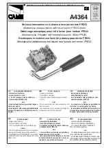
The hosereel must only be lifted by the drum (as shown below), or by the frame


Figure 2 

– Lifting the hosereel 


Summary of Contents for SDM09H

Page 1: ...Product Manual SDM09H Hosereel Issue 2 April 20 Hosereels Hydraulic Rewind Installation and Maintenance Manual Technical Manual No SDM09H...

Page 2: ...enance 4 1 Weekly maintenance 14 4 2 Monthly maintenance 14 4 3 Bi annual maintenance 14 4 4 Corrective maintenance 15 4 5 Swingjoint fluid path assemblies 15 4 6 Problem solving 19 Appendices 1 Layou...

Page 3: ...operational problems or for the supply of spare parts and any technical or usage queries please call our Sales Office on 01480 832200 and they will be pleased to help As soon as you take delivery of a...

Page 4: ...rive gears and chain 3 Centre shaft inlet swingjoint connection 4 Frame 5 Hydraulic motor 6 Hose roller guides if fitted 7 Serial number plate 10 Swingjoint 11 Flexible connection Figure 1 Typical hyd...

Page 5: ...gooseneck assembly are positioned at one end of the hosereel The rewind mechanism may be at either end of the drum assembly The gooseneck depending on the size of the fluid path may be an integral par...

Page 6: ...1 3 3 The total weight of the hosereel requires more than one person to lift or move it and in some installations lifting equipment may be required Lifting instructions are given below WARNING THE CE...

Page 7: ...rewind handle to make sure that there is sufficient space around the hosereel for rotation of the handle It may be necessary to use the manual rewind handle if the power rewind fails for any reason 2...

Page 8: ...angeover valve directs hydraulic power either to the hosereel or cargo pump ii Flow control valve enables the maximum rewind speed to be pre set during installation by adjustment of the flow of hydrau...

Page 9: ...ut EX excess return to tank P supply PR regulated output Figure 4 Valve Port connection Refer to figure 4 above for port connection information Key A Hydraulic supply B Lever operated changeover valve...

Page 10: ...ll providing sufficient friction to prevent overrun of the drum To rewind the hose the brake should be released further When the hose is stored the brake should be fully tightened to ensure that the d...

Page 11: ...kit must be factory fitted The installation must be adequate for the weight of the hosereel and hose Collins Youldon hosereels are not designed for mounting on a vertical surface 2 5 4 Earth continuit...

Page 12: ...also be required under the end of the platform when it is in the parked position Figure 10 Swing out platform 2 5 6 Remote Rewind If the hosereel is supplied with remote rewind adequate guarding must...

Page 13: ...ROLLERS 2 BEFORE COMMENCING THE REWIND OPERATION MAKE SURE THAT ALL OTHER PERSONS ARE STANDING AWAY FROM THE HOSEREEL AND THE HOSE CAUTIONS 1 Ensure that there are no tools or other loose objects nea...

Page 14: ...to trap hands between the rollers 3 4 2 Hinged roller guides Before deploying the hose the roller guide s should be swung into the open position After use and when the hose has been fully rewound the...

Page 15: ...ge and deterioration Look for any swelling under pressure 4 2 5 If fitted check that the earth continuity device is functioning correctly section 2 6 4 4 3 Bi annual maintenance 4 3 1 Check that all f...

Page 16: ...ery hose from the reel however replacement of the spindle and or shaft will require removal of the drum from the frame Leaking product may be due to a worn inlet seal or component The inlet seal may n...

Page 17: ...te in the inlet 4 5 3 5 Apply a little grease to the mating parts of the seal and carefully push the inlet back into position locate with the 3 bolts previously removed taking care not to damage the s...

Page 18: ...and if required fit a new seal into the inlet 4 5 5 3 Apply a little grease to the mating parts of the seal and carefully push the inlet back into position locate with the 3 bolts previously removed...

Page 19: ...bolts and shakeproof washers If the spindle has the O ring type seal take care not to damage the O ring when positioning the inlet 4 5 6 12 Tighten the 3 bolts evenly until secure and reconnect the in...

Page 20: ...unting bolts place packing piece under one corner of the frame and retighten bolts Contact Collins Youldon for advice b Rewind is weak Hydraulic set pressure too low Check setting of controls see c be...

Page 21: ...DRUM HUB SPROCKET C WHEEL SPACER CROWNWHEEL LUBRICATOR KIT PLASTIC GUARD 1 1 16 PLASTIC BEARING 120T SPROCKET SPROCKET SPACER NUT M10 NYLOC NUT ROLLER CORNER BLOCK ROLLER INSERT SHORT ROLLER TUBE SHO...

Page 22: ...FOR 1 5 16 DIA 7605 05 P PLASTIC DRUM HUB FOR 1 1 16 DIA XXXXXXXX XXXXXXXX XXXXXXXX LONG SPACER POWER REWIND AS USED ON POWER REWIND REELS AS USED ON POWER REWIND REELS DRUM WITH STEEL DRIVE PLATE AS...

Page 23: ...2 Dimension D 47 9mm 1 7 8 57 2mm 2 1 4 69 9mm 2 3 4 Swingjoint Assembly fitted with nitrile seals Gunmetal and brass part no 7510 00 B Gunmetal and brass part no 7515 00 B Gunmetal only part no 7515...

Page 24: ...7594 06 B 7594 14 B Gooseneck parallel thread 1 BSPP 10 dia drum Storz coupling 1 BSPP 10 dia drum Storz coupling 1 BSPP 11 dia drum Storz coupling 1 BSPP 15 dia drum Storz coupling 2 BSPP 10 dia dru...

Page 25: ...11 dia drum 2 BST M 11 dia drum 2 BSPT M 15 dia drum 2 BSPT M 19 dia drum 7526 10 A 7526 09 A 7526 16 A 7526 07 A X 7526 10 B 7526 09 B 3 Housing 7526 13 B 4a b Inlet Straight 2 BSP M 90 degree 2 BSP...

Reviews: