Encoder
You must use an encoder to generate pulses as the parts move under the sensor. The way in which you set up your
encoder affects the results from the sensor. Observe the following guidelines when installing your encoder:
l
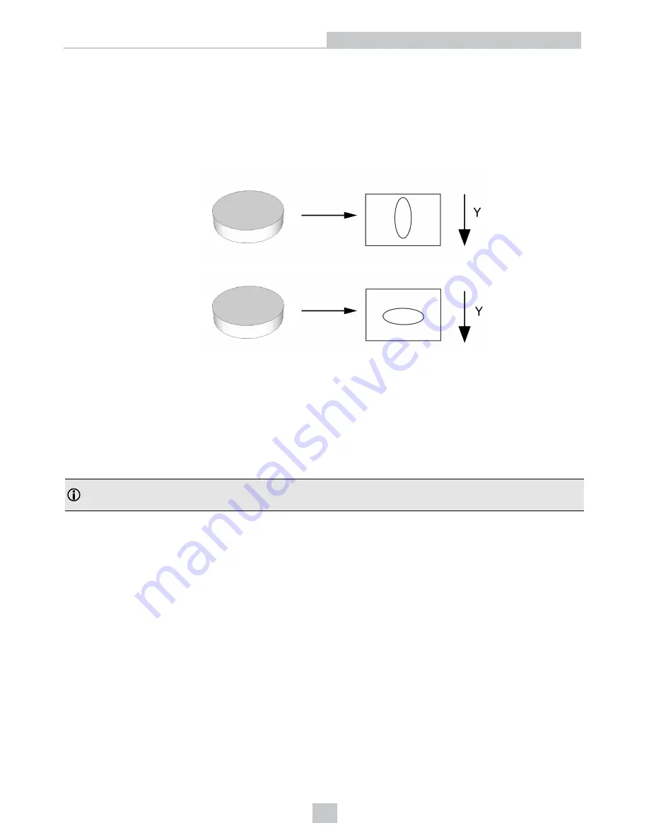
The rate at which encoder pulses are generated, relative to the speed of movement of the surface, will determine
how many slices of height data are acquired per millimeter.
If too many slices are
acquired, the image
will be stretched in
the Y-direction.
If too few slices are
acquired, the image
will be squashed in
the Y-direction.
(
Y-direction
: The axis on which the conveyor belt and the object itself is moving.)
l
For each set of encoder steps per line, the sensor acquires an
intensity image
, locates the laser line, and
generates a row of peak data, which is the basis of a row in the
range image
. The time that it takes for the sensor
to do this is the time that it takes for the encoder to count the number of steps specified in software as
EncoderTriggerCounts
. The duration of this encoder time must always be longer than the time it takes for the
sensor to expose and process one row of data from an intensity image. The time needed to acquire an intensity
image and process it is referred to as the
DS900 Series Line Time
.
Note
: The sensor has its own
software encoder
. This is a good troubleshooting encoder that can be used to verify
the operation of the sensor and diagnose any encoder wiring issues.
29
Encoder
Summary of Contents for DS900 Series
Page 1: ...DS900 Series Displacement Sensors Reference 02 21 2018 Version 9 3 0 5...
Page 14: ...Dimensions DS910B 14 Dimensions DS910B...
Page 17: ...Dimensions DS925B 17 Dimensions DS925B...
Page 18: ...18 Dimensions DS925B...
Page 28: ...28 RS422 Synchronization...
Page 31: ...31 Measuring Field Selection...
Page 42: ...January 2018...


