background image

Digital fire detection control panel 

LYON


 FIRE PROTECTION MANUFACTURER


                                Ctra. de Molins de Rei a Rubí, Km. 8,4 - 08191 RUBÍ (Barcelona) ESPAÑA. 


                                                                Tlf.: +34 935 862 690 - Fax:+34  936 999 261 - [email protected] - 

www.cofem.com

                                       27 


After configuring the control panel, a number must then be assigned to each repeater. This must be 

the same as the one which was configured in the control panel. To do this, follow this sequence in the 
corresponding repeater:    Menu (access code 27) 


1.

 System configuration (access code 9000) 

3-


Repeater number. 


When configuration has been completed, the general system reset must be performed from the 

control panel. To do this, follow this sequence:    Menu (access code 27) 


8- 

General reset. The zone labels 

must then be sent according to this sequence in the control panel: Menu (access code 27) 


1.

 System 

configuration (access code 9000) 


Configure 


Send Zones to Repeaters.


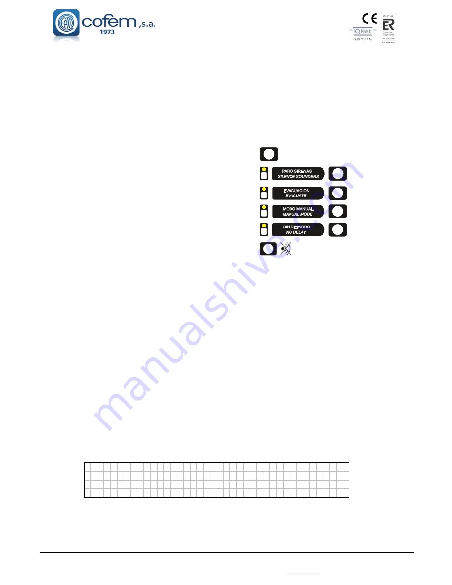
Functions that can be carried out from the repeater: 


Reset alarms and faults. 


RESET


Activate or deactivate silence sounders. 


Activate or deactivate evacuation. 


Activate or deactivate manual mode. 


Activate or deactivate delays. 


Deactivate the buzzer. 


General reset. 


1.5.4.3.- Repeater menus 


The following menus are accessible in the repeater: 


SYSTEM CONFIGURATION 


ADDITIONAL PASSWORDS: From this menu, an additional password can be entered for 
access level 2 and another password for access level 3. Every time a new password is entered, 
the password entered previously will be deleted. The passwords which came pre-installed from 
the factory (access level 2: 

27

; and in access level 3: 

9000

) cannot be deleted.  


LANGUAGES MENU: From this menu, the repeater’s language can be selected. The repeater 
has Spanish, English, French, Italian, Hungarian, Ukrainian and Portuguese pre-installed at 
factory.


REPEATER NUMBER: From this menu, the repeater number to be used when communicating 
with the control panel can be selected. This number can never be used in more than one repeater.


GENERAL RESET: From this option, the whole system can be reset. When the system is reset, all 
the events are deleted from the control panel and the repeaters, i.e. alarms, faults and relay 
actuations. The status of the elements and/or zones that are out of service is maintained.


SYSTEM TEST: This option is used to test the repeater's indicators. In this test, all the leds should 
light up, the buzzer should sound, and the following screen should be displayed:


█ █ █ █ █ █ █ █ █ █ █ █ █ █ █ █ █ █ █ █ █ █ █ █ █ █ █ █ █ █ █ █ █ █ █ █ █ █ █ █
█ █ █ █ █ █ █ █ █ █ █ █ █ █ █ █ █ █ █ █ █ █ █ █ █ █ █ █ █ █ █ █ █ █ █ █ █ █ █ █
█ █ █ █ █ █ █ █ █ █ █ █ █ █ █ █ █ █ █ █ █ █ █ █ █ █ █ █ █ █ █ █ █ █ █ █ █ █ █ █
█ █ █ █ █ █ █ █ █ █ █ █ █ █ █ █ █ █ █ █ █ █ █ █ █ █ █ █ █ █ █ █ █ █ █ █ █ █ █ █


WELCOME MESSAGE: From this option, the welcome message can be changed. The welcome 
message is the text that is displayed in the first line when the repeater is in standby. This message 
can have up to 40 characters. These are entered using the repeater’s cursors or an external keyboard.


Summary of Contents for COMPACT LYON

Page 1: ...MANUAL Digital fire detection control panel Lyon ...

Page 2: ... Point PUCAY 17 1 5 3 Modules 18 1 5 3 1 Master detection module KMAY 18 1 5 3 2 Master relays module MDA1Y 19 1 5 3 3 Master relay module MDA2Y 19 1 5 3 4 Technical signals module MSTAY 21 1 5 3 5 Loop isolator KABY 22 1 5 3 6 Addressable sounder SIRAY SIRAYL SIRAY BSLC 23 1 5 3 7 Master relay and technical signals module MYOA 25 1 5 4 Repeaters 26 1 5 4 1 Installation 26 1 5 4 2 Operation and Co...

Page 3: ...rnal 24V Sounder SIR24F 39 2 3 3 4 Connecting the external 24V alarm box CAE PL 39 2 4 Accessories 40 2 4 1 PC keyboard 40 2 4 2 Computer 41 3 Operation and configuration 43 3 1 Description of the front panel 43 3 1 1 Keypad 43 3 1 2 Light indicators 43 3 1 3 Screen 44 3 2 Access levels 44 3 2 1 Level 1 access 47 3 2 1 1 Activation of the control panel 47 3 2 1 2 Incident and anomaly display 49 3 ...

Page 4: ...ay Setup 58 3 2 3 3 8 Fast Trigger Zone 58 3 2 3 3 9 Send Zones to Repeaters 58 3 2 3 4 Update date and time 58 3 2 3 5 Day Night times 58 3 2 3 6 Put into test normal mode 58 3 2 3 7 Led ON OFF 59 3 2 3 8 Language menu 59 3 2 3 9 Communications 59 3 2 3 10 Stop Sounder Function 61 4 Set up 61 4 1 Prior verifications 61 4 2 Supply 62 4 3 Loops and relays 62 4 4 Faults 63 Annex 1 Use of the Control...

Page 5: ...08191 RUBÍ Barcelona ESPAÑA Tlf 34 935 862 690 Fax 34 936 999 261 cofem cofem com www cofem com 5 3 1 System Programming 73 3 2 Configure 73 3 3 Configure Loop 73 3 4 Loop Configuration 73 3 5 Assign a number to Point 74 4 Programming verification process 74 5 Configure Zones 74 6 Replacing a loop element 75 ...

Page 6: ...ity of operational reliability Vibration resistance Cumple Passed Duración de la seguridad operacional y retardo a la respuesta estabilidad eléctrica Durability of operational reliability electrical stability Cumple Passed Duración de la seguridad operacional y retardo a la respuesta resistencia a la humedad Durability of operational reliability humidity resistance Cumple Passed EN 54 4 Equipo de ...

Page 7: ...ke concentration and the amount of monoxide are sent through the corresponding sensor in electrical voltages related to the measured magnitude After an adaptation process an optimal relationship between the measured magnitude and the electrical voltage is obtained Each sensor incorporates a microprocessor responsible for the digitisation of the analogue value read in the sensor for transmission of...

Page 8: ...the menu handling keys can be found and the other where specific control panel functions may be performed 15 LEDs that enable quick viewing of the control panel status Supply Mode of operation Alarms and Failures Communications port USB 2 0 Access to the interior of the control panel by means of a key Power supply independent module responsible for controlling the Voltage of the primary 30V supply...

Page 9: ... gives values under the real performances of the system For this motive it is necessary to check real capacity of the system by means of the loop elements capacity calculation software when results of using table approximation doesn t allow to satisfy the installation necessities as the real capacity of the system can be higher than expected by the tables To calculate the capacity of the system it...

Page 10: ...ECTION MANUFACTURER Ctra de Molins de Rei a Rubí Km 8 4 08191 RUBÍ Barcelona ESPAÑA 10 Tlf 34 935 862 690 Fax 34 936 999 261 cofem cofem com www cofem com The cable material for the table is Cu with 41 Ω mm2 Km as it is stated in the corresponding note ...

Page 11: ...on and cable lenght 500 m for this case cable lenght is 450 m Following table is obtained Devices in installation Elements equivalence according to table Elements consumption Relays equivalence according to table Relays consumption 136 A30XHAS 1 136 0 17 PUCAY 1 17 0 18 SIRAY 6 108 1 18 TOTAL 171 Elements 261 Elements 18 Relays Comparing these results with the boundaries of the control panel at th...

Page 12: ...rmances by using the table of device limits per control panel It also could have achieved this result using the software directly LYON 450 m 1 5 mm 2 Nº Elements Nº Equipos Model Modelo Sound dB Sonido dB Power Light Potencia Luz 17 PUCAY 0 KMAY 0 MSTAY 0 MDA1Y 0 MDA2Y 0 MYOA 136 A30XHA A30XHAS A30XTA A30XHTCO 0 KABY 18 SIRAY Standard 0 SIRAYL Standard 0 SIRAY BSLC Standard Standard 78 21 171 18 N...

Page 13: ...akes it suitable as a smoke sensor The sensor element is formed by an optical camera provided with an infrared emitter and receiver In the absence of smoke the intensity of infrared caught by the receiver is null due to the physical labyrinth created between the two When smoke is present the infrared reflections from the particles of the same cause the receiver to obtain a certain luminance intens...

Page 14: ...n degree Also in the detection of temperature confirmation by means of two consecutive readings is used less than 10 seconds before activation of the Alarm The operation principle is based on the physical properties of an NTC The variation in electrical characteristics of the thermistor due to the variation of the room temperature is what enables its use as a sensor element The measurement made by...

Page 15: ... labyrinth created between the two When smoke is present the infrared reflections from the particles of the same cause the receiver to obtain a certain luminance intensity Voltage value proportional to the level of obscuration all of which is controlled by the microprocessor system In addition it has a carbon monoxide sensor with a fast response in the presence of CO which is present in the vast m...

Page 16: ...nel LYON FIRE PROTECTION MANUFACTURER Ctra de Molins de Rei a Rubí Km 8 4 08191 RUBÍ Barcelona ESPAÑA 16 Tlf 34 935 862 690 Fax 34 936 999 261 cofem cofem com www cofem com Figure 2 Connection schematic A30XHA A30XTA A30XHTCO and PUCAY ...

Page 17: ...cates the alert status of the button There is a version PUCAYEXT that it is computed by control panel as the activation of 2 simultaneous devices In this way crossed relay L and crossed relay SL can be trigged directly when you push this PUCAYEXT From loop device capacity PUCAYEXT version is considered as a PUCAY The connection is made according to figure 2 The PUCAY is conformant with EN 54 11 wi...

Page 18: ...between conventional smoke detectors A30XH A30XHS and manual call points Both terminals are monitored by an end of line capacitor 10 µF 63V In this way it is indicated an open line crossed line alarm detector or alarm manual call point status The flashing of the transparent red LED indicates communication with the control panel and if it remains on it indicates the alarm status of a detector or ma...

Page 19: ...s recommended installation of an External Power Supply when connecting more than 10 electromagnets altogether per detection system The MDA1Y is conformant with EN 54 18 with the conformity mark awarded by AENOR Connection will be made according to figure 4 Note To determine the number of MDA1Y it can be installed consult the devices limit per control panel table Chapter 1 5 1 5 3 3 Master relay mo...

Page 20: ...l LYON FIRE PROTECTION MANUFACTURER Ctra de Molins de Rei a Rubí Km 8 4 08191 RUBÍ Barcelona ESPAÑA 20 Tlf 34 935 862 690 Fax 34 936 999 261 cofem cofem com www cofem com Figure 4 Connection Schematic Figure 5 Connection Schematic INPUT ...

Page 21: ...ectrical connection through a 33 K resistor which allows indication of open or closed electrical connection status It is typically used to signal the status of other detection systems that may exist as for example connection of flow sensors in the case of sprinkler installations end of travel in the case of fire resistant doors elevators level of deposits etc The flashing of the transparent red LE...

Page 22: ...s and allowing therefore the rest of the loop to operate normally It is supplied installed inside of a high base This assembly allows having it in the same place as the detector making easy the connection of the loop wiring The base has two stickers in the outer side with the word KABY to allow easy recognition The element is feed from the loop connection The KABY is conformant with EN 54 17 with ...

Page 23: ...trol panel For this reason these devices are programmed in the control panel as it was SIRAY The standard configuration of the sound of the siren is shown in Figure 8A according to EN 54 3 sounder In the same figure the standard configuration of the light signal in the socket of the SIRAY BSLC siren according to EN 54 23 visual alarm device is shown It is allowed to change the selection of the ton...

Page 24: ...x2 5mm2 1350 m 2x2 5mm2 SIRAY 32 8 16A 6 12A 4 8A 32 4 8A SIRAYL 32 10 20A 8 14A 6 10A 25 6 10A SIRAY BSLC 19 25 35 40B 16 24 26B 12 20 22B 10 12 20 22B Addressable sounder Addressable sounder with light Addressable sounder with EN 54 23 light A Values correspond with the standard maximum sound intensity of the sounder B Value corresponds with the sound light standard sound or light at maximum sou...

Page 25: ... realy is 30 V The technical signal input has a 10 K resistor connected in serie with the dry contact In quiescent condition the contact has to be open and in anomaly condition the contact has to be closed In the input marked with IN2 the closed contact is detected as ALARM condition The MYOA supervises each external line relay ouput and technical signal input through a 33 K each one which allows ...

Page 26: ...f the corresponding repeaters The repeaters must be connected as shown in figure 11 Up to 3 repeaters can be connected to the Lyon control panel s power supply 30V output From 4 to 15 repeaters must be fed from the 30V output of an auxiliary power supply FAE For connecting the repeaters both the communication and 30V power supply cables must be 2 x 1 5 mm HALOGEN FREE SCREENED BRAIDED CABLE up to ...

Page 27: ...TIONAL PASSWORDS From this menu an additional password can be entered for access level 2 and another password for access level 3 Every time a new password is entered the password entered previously will be deleted The passwords which came pre installed from the factory access level 2 27 and in access level 3 9000 cannot be deleted LANGUAGES MENU From this menu the repeater s language can be select...

Page 28: ...ction control panel LYON FIRE PROTECTION MANUFACTURER Ctra de Molins de Rei a Rubí Km 8 4 08191 RUBÍ Barcelona ESPAÑA 28 Tlf 34 935 862 690 Fax 34 936 999 261 cofem cofem com www cofem com Figure 11 Repeater connection ...

Page 29: ...etwork by connecting 2 wires of 1 5 mm2 RS485 communication line The two wires of the RS485 line will be connected from the CONRED indication in the back panel of each control panel Such connections are shown in Figure 13 Power is held in each control panel separately Each control panel will be connected to the 110 230V mains and its corresponding set of batteries The communication cables connecti...

Page 30: ...f the control panels of the network Reset alarms and faults in the network control panels Reset all the network control panels Enable or disable without delay mode in all network control panels Enable or disable sirens stop in all network control panels Enable or disable the evacuation in all network control panels Enable or disable manual mode in all network control panels Disable the buzzer in a...

Page 31: ... cofem cofem com www cofem com 31 Figure 13 Control panels network connection BACK PANNEL A B A B CONRED CONCPU CONEXTENSION Central Control Panel Centrale LYON Nº1 Central Control Panel Centrale LYON Nº3 Central Control Panel Centrale LYON Nº2 BACK PANNEL A B CONRED CONCPU CONEXTENSION 120 central más alejada BACK PANNEL A B CONRED CONCPU CONEXTENSION 120 primera central ...

Page 32: ...ns of which the user can perform all the control panel programming in a simple and intuitive way With this system it will be possible to maintain the configuration for future use The minimum configuration of the PC is 1 8 GHz Windows 7 8 10 2 GB of RAM 1 GB free space on the hard disk DirectX9 Minimum resolution 1024x768 Free USB port 2 Installation 2 1 Control panel installation The control panel...

Page 33: ... completely finished and clean A list must be made for each loop with the location type and programming number of each element this programming number goes from 1 to the 65533 see the example in the following table Loop 01 POINT Programming no Label Type Notes 1 12757 ROOM 101 A30XHA 2 12432 ROOM 102 A30XHA 3 4767 BUTTON P1 PUCAY 4 6982 CORRIDOR P1 MDA1Y DISCONNECT the 110 230V Voltage circuit and...

Page 34: ...with two joined boxes providing a maximum of 20 loops 35V Supply Driver controller connection LOOP 1 LOOP 2 Figure 16 Loop driver Each loop driver is numbered to identify the corresponding loop The numbering and the polarity come on the strip connector Connection of the loops of the Lyon analogue system will be made with 2 x 1 5 mm BRAIDED SCREENED HALOGEN FREE CABLE for lengths of up to 800 metre...

Page 35: ...d by means of the configuration menu see 3 chapter configuration The installation of sirens will be performed according to the schematic of figure 19 It will be activated whenever an alarm occurs in the system and the programmed delay has passed It is only deactivated when there is no alarm in the system S2 Sounder Unmonitored voltage free output exit It is activated whenever an alarm occurs in th...

Page 36: ... loops and additional loads e g relays modules 7Ah being the minimum recommended Batteries with a capacity of 15Ah or 24Ah will have to be housed in a box external to the control panel ref C 55 Connection of the two 12V batteries in series is exactly as indicated in figure 18 Power supply Figure 18 Battery connection schematic 2 3 2 Connection schematic of a typical loop Connection of the Lyon ana...

Page 37: ...tion control panel LYON FIRE PROTECTION MANUFACTURER Ctra de Molins de Rei a Rubí Km 8 4 08191 RUBÍ Barcelona ESPAÑA Tlf 34 935 862 690 Fax 34 936 999 261 cofem cofem com www cofem com 37 Figure 19 General Wiring Diagram ...

Page 38: ...rol panel and or modules 1 Diode BY252 two diodes are included with each control panel Lyon system Figure 20 SIR 24B SIR 24BL connection schematic NOTE An auxiliary 30V supply is necessary for MYOA MDA1Y and MDA2Y modules 2 3 3 2 Connection of the non flashing internal 24V Sounder SIR24P Elements needed for its correct installation 1 Resistance of 33 KΩ in the event of the sounder being connected ...

Page 39: ...the general sounder the resistance should be 4K7 which is included in the control panel and or the modules 1 BY252 Diode two diodes are included with each Lyon control panel Figure 22 CAE24V Connection schematic 2 3 3 4 Connecting the external 24V alarm box CAE PL Elements needed for its correct installation 1 33 KΩ Resistance in the event of the sounder being connected to the general sounder the ...

Page 40: ...aters from the MAINS 110 230V and the BATTERIES before connecting the external keyboard ES C F9 F1 1 F1 2 1 2 3 4 5 6 7 8 9 0 Pg Up Q W E R T Y U I O P Enter Pg Down 7 8 9 Caps Lock A S D F G H J K L 4 5 6 Z X C V B N M Up 1 2 3 Ent er SPACE Lef t Dwn Rght 0 F9 Silence buzzer F11 Menu F12 Reset Pag Go forwards three options in any menu and one loop in the monitoring screen Pag Go backwards three o...

Page 41: ...1 8 GHz Windows 7 8 10 2 GB of RAM 1 GB free space on the hard disk DirectX9 Minimum resolution 1024x768 Free USB port As shown in the diagram the connection between the PC and the control panel must be made using a USB 2 0 PORT The use of the I Link program and the configuration of the communication ports of the computer are described in the manual Manual I Link In the case of installing the func...

Page 42: ...ACTURER Ctra de Molins de Rei a Rubí Km 8 4 08191 RUBÍ Barcelona ESPAÑA 42 Tlf 34 935 862 690 Fax 34 936 999 261 cofem cofem com www cofem com Example of PC connection I Link ONLINE with LYON control panel through a RS232 RS485 converter or using TCP IP connection ...

Page 43: ...appears on the screen and to select characters in text mode ESC Key that enables the user to pass from one level to a higher level in the menu tree of the control panel and to cancel menu selections MENU This key enables us to enter the control panel menu and to show the help text of the various menus ENTER This key enables us to confirm a selection SILENCE BUZZER RESET Key that enables the user t...

Page 44: ...h C D A n L Y O N C o f e m s a MO D E MO D E 1 2 0 8 0 6 N I G H T A U T OM A T I C 1 0 2 9 3 2 Access levels The control panel has four levels of access Level 1 allows the control panel to be manipulated in its most basic functions such as silencing the buzzer or review of the incidences that the control panel has been able to detect Level 2 it is only accessible by maintenance personnel by mean...

Page 45: ...17 1 Sensitivity of a type 2 Flashing Menu 31 1 Flashing permitted 2 Flashing inhibited 3 View configuration 3 POINT configuration Menu 32 1 View loop information 2 Search for loop elements 3 Assign number to element 4 Loop auto configuration 5 Delete point 6 Replace point 7 Delete loop points 2 Configure logical relays Menu 18 1 Relay actuation 2 Delay 3 Day night Menu 33 1 Prog day button 2 Prog...

Page 46: ...ngarian 6 Language Ukrainian 7 Language Portuguese 8 Communications Menu 15 1 Network of repeaters Menu 24 1 Configure repeaters 2 Auto detect slaves 3 Delete repeater 4 Label repeater 5 Delete repeaters 6 Label repeater 2 Internal network Menu 25 1 View control panels 2 Program control panels 3 Especial functions Menu 35 1 Disable delays 2 Disable sirens 3 Evacuate 4 Manual mode 3 ContactID Menu ...

Page 47: ...panel If the control panel is starting up correctly we see C D A L y o n V 2 V x x C C o f e m S A I n i c i a n d o a r r a n q u e V X X corresponds the version number of the control panel s software The control panel is looking at the previous configuration data R e c o v e r i n g p r e v i o u s c o n f i g u r a t i o n Z o n e s R e l a y s U p d a t i n g s y s t e m The control panel is p...

Page 48: ...s t l o o p c o n t r o l l e r P r e s s E N T E R t o c o n t i n u e 4 In the event of continuing from the previous message and of continuing without a loop controller we will have the two options that are seen in the following figure to reinitiate the control panel or to continue and to start up the control panel without a configured loop controller C OM U N I C A T I O N E R R O R L O O P C O...

Page 49: ... E 0 1 L A B E L M C P T 0 1 0 1 If the right cursor is pressed we will be able to see the rest of the alarm information Unit Loop POINT A L A R M S C B P t 0 1 Z 0 0 1 L A B E L 0 1 0 1 0 0 6 0 1 0 2 Nº of alarmed zone Selected alarm Nº alarms Relays on If the control panel actuates a relay it will illuminate the amber RELAYS ON LED sound the buzzer and show the following message T R I G G E R R ...

Page 50: ... L Y C O N T R O L 1 1 H I G H V N E T 0 1 0 2 Within supply faults the following types of fault exist Type of Fault Description 30V Fault in the 30V output NO BATTERY Battery fault due to or absence of batteries CHARGER FAULT Battery charger fault FAULT CHARGER Battery charger fault BAT OVERCHARGED Battery fault due to high Voltage level HIGH VOLTAGE Network Voltage fault due to exceeding the lev...

Page 51: ...the two outputs is at fault R1 and R3 marked as 01 and 03 Within the general outputs faults there are these types of faults Type of fault Description SC RELAY Nº Short circuit in the general soundern relay or general fault relay OC RELAY Nº Open circuit in the general sounder relay or general fault relay 3 2 1 3 Moving through incidents Once the control panel has displayed any of the incidents des...

Page 52: ...ents After any of the incidents previously described have been detected and the access code to level 2 has been entered pressing the RESET key will deactivate these incidents thereby resetting them If these incidents were faults before resetting we must ensure that they have been corrected otherwise they will re appear on the screen 3 2 2 4 Monitor Option 1 of the main menu MONITOR It enables the ...

Page 53: ...tivate general relays Option 3 of the main menu GENERAL RELAYS ACTIVATION In this menu we have 2 submenus GENERAL SIREN RELAY FAULT RELAY Within each of these we have 5 options ACTIVATE RELAY DEACTIVATE RELAY CHANGE DELAY DISABLE RELAY and ENABLE RELAY Exactly as they suggest the submenus enable us to activate or deactivate the relay to configure its delay between 0 and 9 minutes 59 seconds and di...

Page 54: ...onological order from the most recent to the oldest storing a maximum of 4095 events Once 4095 events are stored the control panel will automatically delete the oldest in order to store a new event Review complete history This enables each of the incidents detected by the control panel to be reviewed understanding by incident disabled alarms faults zones and elements and actuations of relays Revie...

Page 55: ... I C E M E N U C O P Y R E S E T P A S T E E N T E R A C C E P T In order to introduce the label we can use the control panel cursors or an external keyboard 3 2 3 3 Configure Option 2 of the SYSTEM CONFIGURATION menu 3 2 3 3 1 Loop configuration Option 1 of the CONFIGURE menu In this menu we have the possibility of configuring all the parameters related to the element of a loop such as to assign ...

Page 56: ... so configured and this is affected by the silence sounders button MANOEUVRES these are activated automatically if they have been so configured and are not affected by the silence sounders button Crossed Relay L this is activated automatically when there is 2 devices in alarm inside its activation List It is not affected by the silence sounders button neither evacuation button Crossed Relay SL thi...

Page 57: ...We will be able to introduce 8 lists into each alarm zone MODIFY LISTS This option allows us to modify one of the alarm zone lists DELETE ZONE The zone configuration is deleted LABEL This provides a description of the zone with a maximum of 20 characters for its identification in the installation VIEW CONFIGURATION To view the list of points that are included in the alarm zone Label Zone number Z ...

Page 58: ...introduced in this option makes immediately activation of all control panel relays 3 2 3 3 9 Send Zones to Repeaters This is option 9 of the CONFIGURE menu This option allows sending the configured zones to the repeaters of not realising it the repeaters will only indicate the label of the point 3 2 3 4 Update date and time This is option 3 of the SYSTEM CONFIGURATION menu Within this menu we have...

Page 59: ...h French Italian Hungarian Russian Ukrainian and Portuguese 3 2 3 9 Communications This is option 8 of the SYSTEM CONFIGURATION menu Within this menu we have following submenus NETWORK OF REPEATERS VIEW CONFIGURED REPEATERS display the configured repeaters on the control panel CONFIGURE REPEATERS Give the address of the repeaters with which it is desired to communicate AUTO DETECT SLAVES In this m...

Page 60: ...T CONTROLLERS In this menu all the connected controllers are detected and configured This function deletes the previously configured controllers ERASE LOOP CONTROLLER Erase the selected loop controller from the configuration of the control panel ERASE SUPPLY CONTROLLER To erase the selected power supply controller from the configuration of the control panel CONSULT VERSION Check the software versi...

Page 61: ...en completed To have a 110 230V power source available dedicated to the fire protection system and that it is live 24 hours a day seven days a week see chapter 2 1 To have a set of two 12V batteries with a capacity between 7 and 24Ah depending on the number of loops and load connected to the control panel to see chapter 2 3 1 To verify that all the elements are connected to the installation To ver...

Page 62: ...the putting on operation If the number found is lower it means that fewer elements have been installed in the loop there are unconnected or not assembled loop elements Review the whole loop installation reviewing all the connections and counting the installed elements Once any problems in the system have been resolved the loop element search must be repeated If a correct result is obtained the ent...

Page 63: ...ndled ensuring that it is correctly inserted in the back panel and that the micro switches are configured as in the following table Controller 1 Controller 2 Controller 3 Controller 4 Controller 5 Also consult section 3 2 1 1 CONTROLLER NOT FOUND WITH ADDRESS 001 002 003 004 005 Cause During the control panel s start up process the panel had not found the Loop Controller with the number indicated ...

Page 64: ...Cause The batteries have reached the end of their useful life Solution Replace the set of batteries with new ones For normal operation the voltage in the battery output when they are connected should be between 22V and 28V See chapter 2 3 1 BATTERIES DISCHARGED The batteries are not charged Cause The batteries are not charged or they are not connected correctly Solution Check that the two 12V batt...

Page 65: ...CUIT 03 Open circuit for the S3 General Fault relay Cause There is a lack of continuity between the output of the S3 General Fault relay and the end of line resistance Solution Check that the S3 General Fault output is correctly connected to the devices connected to it check that the end of line resistance 4K7 and the supervision diodes are correctly mounted Check the status of the S3 output fuse ...

Page 66: ... Department OPEN CIRCUIT IN MASTER Open Circuit in the KMAY master for conventional detectors Cause There is a lack of continuity in the wires for the line of slaves from the KMAY to the end of the line The end of line is not mounted Solution Check that the KMAY is correctly connected to the detectors and manual call points which are connected to it Check that the end of line 10uF 63V condenser is...

Page 67: ... diodes are correctly mounted see chapter 1 5 3 2 To operate correctly the output voltage of the relay 2 of the MDA2Y must be between 2 V and 7 8 V when in standby and between 24 V and 29 V when activated 24V RELAY 24V Fault in module MDA1Y MDA2Y or MYOA Cause The 24 V voltage does not reach the module from the power supply s 30 V output which may be from the control panel or from an auxiliary ext...

Page 68: ...ean the sensor using compressed air reset the fault and monitor the element checking that the readings are below 5 If the levels are higher or the dirty sensor fault is repeated cleaning it has not been sufficient and it is recommended that the sensor is replaced with a new one 4 4 4 OTHER FAULTS ELEMENT NOT FOUND In the monitoring screen Cause The loop point indicated cannot be found by the contr...

Page 69: ...ing of the event and acting on various elements such as emergency exit doors acoustic fire alarms or crossed outputs 2 Front panel of the system This is what the control panel of the centralised LYON system looks like The keys enable action to be taken via the control unit while the luminous indicators LEDs and the screen provide information about the system status 3 What happens if the buzzer sou...

Page 70: ...unction can be performed once the keypad has been enabled and by pressing the evacuation key IMPORTANT This must be confirmed with the ENTER key This function activates all sirens and switches in the system This is also shown by lighting the luminous indicator 6 SILENCE SIRENS When required this function enables the sirens to be silenced The keypad must be enabled and it is performed by pressing t...

Page 71: ...el This number is assigned at the factory When an element search operation is conducted using the control unit it finds all the loop elements memorising the type of element and the assigned programming number The basic purpose of this procedure is that by conducting this search all these numbers can be passed to the control unit memory and for them to be assigned to the loop where the search was c...

Page 72: ...ill show the main menu on the display KEYS FOR NAVIGATING THE MENUS ESCAPE KEY ENTER KEY Return to previous screen Confirm menu options By using the arrow keys the menu options below will be displayed 1 Monitor 2 Logical relay activation 3 General relays 4 System configuration 5 Elements zones in out of service 6 System test 7 Welcome message 8 General reset SIN RETARDO NO DELAY PARO SIRENAS SILEN...

Page 73: ... of the loop to be configured The following menu with 3 options will appear on the display 1 Sensitivity of a type 2 Flashing 3 Point configuration 3 4 Loop Configuration The first step is to configure the elements of the loop so that the control unit recognises all the Elements that are connected to each of the loops By selecting option 3 Point Configuration the option will be the first to appear...

Page 74: ...Select with the ENTER key Firstly you will be asked for the number of the loop and then the programming number of the element Check that the information shown is correct With the arrow keys it is possible to change from one point to another With the arrow keys it is possible to change from one loop to another 5 Configure Zones The purpose of an alarm zone is to provide more complete information an...

Page 75: ...the loop PROGRAMMING number of the loop element 2 Make note of the loop configuration See chapter 3 4 Loop Configuration It is option 1 on the element configuration menu 3 Delete the point removed from the loop See chapter 3 4 Loop Configuration It is option 5 of the element configuration menu 4 Insert the new element having previously made note of the programming number 5 Search loop element When...

Page 76: ... com sat1 cofem com ventas1 cofem com ventas2 cofem com cofem cofem com Atención Técnico Comercial Ventas 34 902 448 811 34 935 862 690 C S Sales 34 935 862 694 34 902 338 811 sat2 cofem com tecnic cofem com compras cofem com export cofem com Export Fax pedidos S A T Compras 34 935 862 692 34 935 862 693 Technical Commercial Service T A S Purchase Export 34 902 338 811 34 936 999 261 Fax pedidos F...

Reviews: