


48
The easiest way to measure squish clearance is with 1mm to 1.5mm thick
flexible solder wire (available through most popular electronic stores). The
process is as follows:
Assemble the top end of the engine with either; 1) the crankcase stamp
recommended base gasket or, 2) if assembling with a new set of cases
assemble with a 0.4mm (0.015”) base gasket, and torque the head nuts to the
proper torque specifications leaving off the spark plug and ignition cover
(piston rings can be left off to ease of assembly).
Carefully insert the solder wire though the spark plug hole, into the cylinder
far enough such that the tip of the wire touches the left or right side cylinder
wall (not the front or back as the piston will rock more and give incorrect
measurement).
Hold the wire at this position and rotate the crankshaft, by the flywheel nut (or
kick lever) three revolutions to crush the solder wire.
CAUTION:
If you rotate the flywheel nut in a counterclockwise direction there is a risk of
loosening the nut.
Pull out the wire and measure the solder thickness at the thinnest location
near its tip accurately with the thin tips of calipers.
Adjust base gasket thickness as necessary to get the desired value.
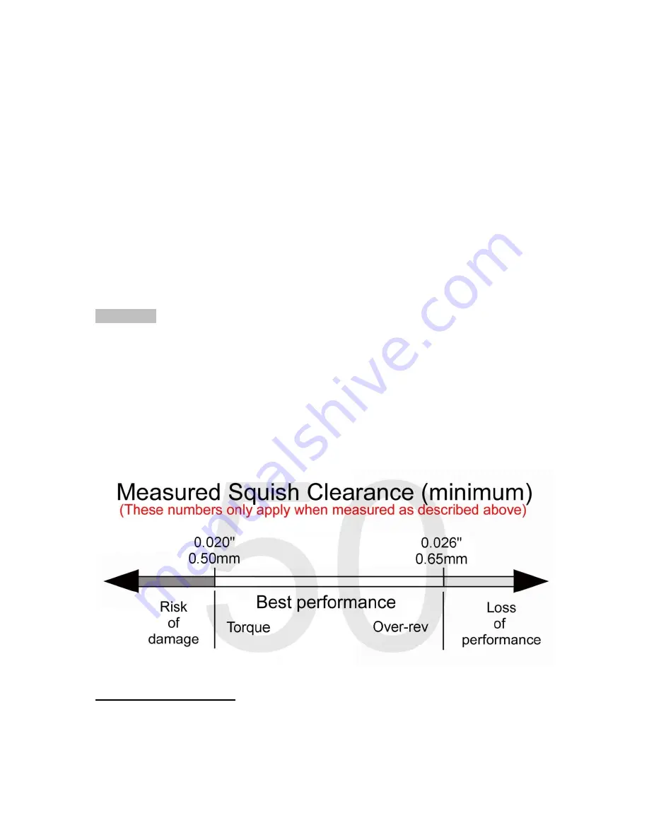
Upon completion, your final assembly squish clearance should agree with the
chart below:
CFD Adjustment
This section tells you what to do if you have tested and determined that the CFD
requires adjustment.
Summary of Contents for CX50P3
Page 23: ...23 This Page Intentionally Left Blank...
Page 24: ...24 Parts Engine Bottom End and Transmission...
Page 26: ...26 Parts Engine Clutch and Kick Lever...
Page 31: ...31 This page left intentionally blank...
Page 32: ...32 Parts Forks Triple Clamps...
Page 34: ...34 Parts Forks Leg Assembly...