29
CHA/IK
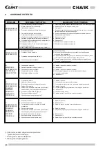
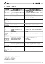
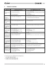
1. Check the voltage at the ends of the contactor coil and the continuity
of the coil. Replace if faulty.
2. Inspect the insulation between the windings and between the windings
and the earth.
3. Check and tighten.
4. Check and replace if necessary.
1. After pressurising the circuit at about 10 bar, check with a leak tester.
Repair, depressurise and
fill
with refrigerant liquid.
1. See previous point (VII).
1. Replace the
filter
cartridge or the
filter
(depending on the model).
1. See point VII.
2. Inspect and replace or overhaul.
3. Reduce the heat load.
4. Check the thermostat set-point and replace the thermostat if necessary.
5. Replace.
1. See point VII.
2. Empty the cooling circuit, dry it, replace the
filter
- do the charge again
1. Check, clean and replace if necessary.
2. See point VII.
3. Clean or replace.
4. Inspect the pump and replace it if necessary.
1. Check valve coils. Replace the inversion valve if necessary.
2. Change the set-point or replace the probe if necessary.
1. Check and replace if necessary.
2. Check and add refrigerant liquid.
3. Fix the pipes with brackets.
4. Install correctly.
1. Fan contactor is not energised
2. The fan thermal cut-outs trip (+)
3. The connections are faulty
4. The fan motor is faulty
1. There's a leak in the refrigerant circuit
1. There's not enough refrigerant liquid in the circuit
1. The
fluid
filter
is clogged
1. Lack of refrigerant gas
2. Compressor not performing as expected
3. The heat load is excessive
4. The thermostat is badly adjusted or broken
5. The liquid
filter
is clogged
1. There isn't enough refrigerant liquid
2. Moisture in the refrigerant circuit
1. The thermostatic expansion valve doesn't work properly
2. There isn't enough refrigerant liquid
3. The
filter
on the liquid line is clogged
4. The water circulation pump is faulty *
1. The 4-way inversion valve is not energised**
2. The defrosting thermostat set-point is incorrect or the
probe is faulty **
1. The compressor is noisy
2. The thermostatic valve is noisy
3. There are vibrations in the piping
4. The panels vibrate
VI.
THE FANS DON'T
START
VII.
LACK OF
REFRIGERANT
LIQUID
VIII.
THE FLUID PIPE
IS HOT
IX.
THE FLUID PIPE IS
COVERED WITH
FROST
X.
THE UNIT CONTI-
NUES TO WORK
WITHOUT
STOPPING
XI.
THE UNIT WORKS
REGULARLY BUT
HAS AN INSUFFI-
CIENT OUTPUT
XII.
THE COMPRESSOR
SUCTION LINE IS
COVERED WITH
FROST
XIII.
THE DEFROSTING
CYCLE IS NEVER
ACTUATED
XIV.
ABNORMAL NOISE
IN THE SYSTEM
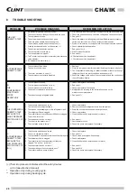
PROBLEM
POSSIBLE REASONS
RECOMMEN DED ACTION
(+) The microprocessor indicates when the safety devices
cut in (see attached manual).
* Operation only during cooling cycle.
** Operation only during heating cycle.
8
TROUBLE SHOOTING


