


16
CHA/IK
5.2
WATER CONNECTIONS
5.2.1 General
Please carefully carry out the following instructions and
observe current law when installing the chilled water
circuit.
Attention!
The water pipes must be suitably supported
with brackets in order not to weigh on the
chiller.
- Connect the pipes to the chiller with flexible joints in
order to prevent the transmission of vibrations and to
compensate thermal expansion.
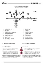
- Install the following components on the pipes:
• shut-off valve (moisters) for shutting off the water
mains;
• temperature and pressure gauges for routine main-
tenance and inspection purposes;
• check points on the inlet and outlet pipes for meas -
uring temperatures if temperature indicators are not
fitted;
• metal filter (inlet pipe) with a maximum mesh aperture
of 1 mm to protect the exchanger from waste or
impurities in the pipes;
• waterflow control valve
• relief valves, fitted in the uppermost parts of the
water circuit, for expelling air;
• eventual supplementary expansion tank of a suit-
able size for the quantity of water contained in the
system and the expected temperature range.
•
an automatic inlet valve for maintaining the pres -
sure of the system and compensating the thermal
expansion of the fluid.
5.2 PRZYŁĄCZA WODNE
5.2.1 Ogólne wytyczne
Wykonując instalację wody lodowej, należy dokładnie
wykonać poniższe instrukcje, zgodnie z obowiązującymi
przepisami.
Uwaga!
Przewody instalacji wodnej muszą być od-
powiednio zamocowane na wspornikach aby
uniknąć przeciążenia agregatu.
- Podłącz przewody do agregatu za pomocą złączek
elastycznych aby zapobiec przenoszeniu wibracji i dla
zrównoważenia rozszerzalności cieplnej.
- Instalację należy wyposażyć w następujące elementy:
• zawór odcinający (zasuwa) główny dopływ wody;
• manometry temperatury i ciśnienia dla celów rutyno-
wych przeglądów;
• punkty kontrolne na wlocie i wylocie instalacji do po-
miaru temperatury, jeżeli nie zamontowano czujników.
• filtr metalowy (na wlocie) z maksymalną wielkością
oczek siatki 1 mm, dla zabezpieczenia wymiennika
przed odpadami lub nieczystościami obecnymi w
instalacji.
• zawór kontrolny przepływu wody;
• zawory odpowietrzające, montowane w najwyższym
punkcie obiegu wodnego.
• ewentulanie, dodatkowe naczynie wzbior-
cze o wielkości odpowiadającej ilości wody
obecnej w układzie i dla przewidywanego
zakresu temperatur.
• oraz automatyczny zawór wlotowy do podtrzymy-
wania ciśnienia w układzie i wyrównywania rozsze-
rzalności cieplnej cieczy.