


Model 21 -CET-6
ServiceManual
21. BIowdown the steam generator by pressing the POWER switch to OFF.
22. After the steam generator has drained, flush it once more by pressing the
POWER switch ON, waiting for the steam generator to fill (about 3-4
minutes), and then pressing the POWER switch to OFF.
23. After the steam generator has drained, the SteamCraft 3.1 is ready for
operation as desired.
NOTE:
Contact service representative or manufacturer for descaling kits or
for information on descaling procedures.
YEARLY MAINTENANCE
Page 59
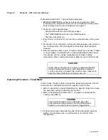
Figure 4-2. Water Strainer Assembly
Clean Water Line Strainer
NOTE:
If water quality does not meet the standards of Table 2-2 on page 7
and a SteamerGard has not been installed, the strainer may need to
be cleaned more frequently than once a year. When the steamer is
first installed, check the strainer more frequently to find out how
often it must be cleaned.
Clean the water line strainer at least once a year as follows:
1. Close the valve(s) in the steamer water supply Iine(s).
2.
Unscrew the filter cap from the bottom of the strainer. Refer to Figure 4-
2.
3. Remove the filter screen and wash it with clean water.
4. Check the 0-ring for wear and replace it if necessary.
5. Put screen back into cap and replace the cap in the strainer.
6. Open water supply valve(s) and check for water leaks.
Printed 12/90
Summary of Contents for steamcraft 21-CET-8
Page 9: ......
Page 53: ...Model 21 CET 8 Service Manual Page 45 Printed 12 90 ...
Page 104: ...Model 21 CET 8 Service Manual Page 97 Printed 12 90 ...
Page 109: ...Figure 6 1 Major Component Groups Printed 12 90 ...
Page 112: ...Page 106 21 CET 8 Service Manual Figure 6 3 Steamer Compartment Group Printed 12 90 ...
Page 114: ...Figure 6 4 Compartment Door And Hinge Assemblies Printed 12 90 ...
Page 120: ...Page 114 21 CET 8 Service Manual Figure 6 7 Electrical Components Assembly Printed 12 90 ...
Page 122: ...Figure 6 8 Steam Generator Assembly Printed 12 90 ...
Page 124: ...Figure 6 0 Heater Assembly Printed 12 90 ...
Page 130: ...Figure 6 11 Water Inlet System Printed 12 90 ...
Page 132: ...Figure 6 12 Condenser And Drainage Systems Printed 12 90 ...
Page 134: ...Figure 6 13 Equipment Stand Printed 12 90 ...
Page 136: ...Figure 6 14 SteamCraft 3 1 Wiring Diagram Electronic Time Printed 12 90 ...
Page 137: ...Figure 6 15 SteamCraft 3 1 Schematic Diagram Electronic Timer Printed 12 90 ...
Page 138: ...Figure 6 16 SteamCraft 3 1 Wiring Diagram Mechanical Timer Printed 12 90 ...
Page 139: ...Figure 6 17 SteamCraft 3 1 Schematic Diagram Mechanical Timer Printed 12 90 ...