background image

OPERATION

16

T12 9009918 (3--2013)

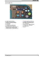
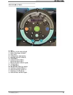
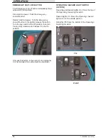
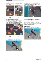
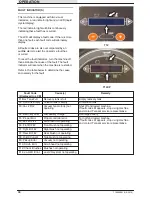
CONTRAST CONTROL BUTTON

Use the

Contrast control button

to darken / lighten

the LCD display.

T12

T12XP

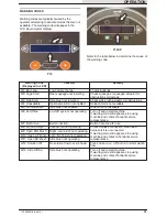
CONFIGURATION MODE BUTTON

The

Configuration mode button

is for accessing

the configuration and diagnostic modes. Only

properly trained service personnel and TENNANT

representatives should access these modes.

T12

T12XP

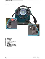
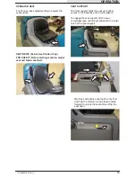
PROPEL PEDAL

Press the

Propel pedal

to move the machine.

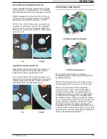
DIRECTIONAL SWITCH

Use the

Directional switch

to select either the

forward or reverse direction. Press the propel

pedal to move the machine.

NOTE: An audible alarm will sound when the
Directional switch is placed into reverse.

NOTE: Machines equipped with the optional
flashing light / backup alarm only: The optional
backup light and alarm will function only when the
machine is moving in reverse.

BRAKE PEDAL

Press the

Brake pedal

to stop the machine.

Summary of Contents for TENNANT T12

Page 1: ...T12 SCRUBBER DRYER OPERATOR MANUAL Clemas Co Unit 5 Ashchurch Business Centre Alexandra Way Tewkesbury Gloucestershire GL20 8NB Tel 01684 850777 Fax 01684 850707 Email info clemas co uk Web www clema...

Page 2: ...ard FOR SAFETY 1 Do not operate machine Unless trained and authorized Unless operator manual is read and understood Under the influence of alcohol or drugs While using a cell phone or other types of e...

Page 3: ...ery acid Battery installation must be done by trained personnel All repairs must be performed by a trained service mechanic Do not modify the machine from its original design Use Tennant supplied or a...

Page 4: ...ecovery tank D Rear squeegee E Main brush compartment F Side squeegee G Vacuum wand Option H Solution tank drain hose I Recovery tank drain hose J Spray nozzle Option K Rear squeegee protector Option...

Page 5: ...ENTS T12 A D B C H G J E F I A Steering wheel B Touch panel C Propel pedal D Brake pedal E Spray nozzle switch Option F Operating lights hazard lights switch Option G Side brush switch Option H Key sw...

Page 6: ...t D LCD display E Hour meter F Configuration mode button G Recovery tank full indicator H Brush pressure decrease button I Brush pressure indicator lights J Brush pressure increase button K Solution d...

Page 7: ...TS T12XP H B A D C E F G I J A Steering wheel B Touch panel C Propel pedal D Brake pedal E Emergency shut off button F Directional switch G Key switch H Spray nozzle switch option I Side brush switch...

Page 8: ...cator D Hour meter E Configuration mode button F Recovery tank full indicator G LCD display H Contrast control button I Brush pressure button J Brush pressure indicator lights K 1 Step button L ec H2O...

Page 9: ...n squeegee Operating lights 1 STEP Hazard light ec H2O option Scrub mode Solution flow Circuit breaker Increase Spray nozzle option Decrease On Main brush pressure Off Side brush option Solution On Of...

Page 10: ...Operate the machine a few minutes before reading the charge level of the batteries NOTE The flashing Warning fault indicator and battery low fault in the LCD liquid crystal display will not reset unt...

Page 11: ...n the key switch to the Off position then turn the key fully clockwise and release it to the On position Only use this button in the event of an emergency It is not intended for routine machine shutdo...

Page 12: ...at and fasten seat belt SEAT SUPPORT The Seat support holds the seat up to allow access to the batteries and circuit breakers To engage the seat support lift the seat completely open until the pin sli...

Page 13: ...s these modes T12 T12XP PROPEL PEDAL Press the Propel pedal to move the machine DIRECTIONAL SWITCH Use the Directional switch to select either the forward or reverse direction Press the propel pedal t...

Page 14: ...The solution indicator lights will turn back on and the solution flow will default to the last setting used T12 T12XP HOW THE MACHINE WORKS T12 With Cylindrical Brushes T12 With Disk Brushes The 1 ST...

Page 15: ...er AB brush Cylindrical and Disk Nylon fiber with an abrasive grit to remove stains and compacted dirt Aggressive action on any surface Performs well on buildup grease or tire marks This brush is also...

Page 16: ...te machine in areas where the ambient temperature is above 43_ C 110_ F Do not operate scrubbing functions in areas where the ambient temperature is below freezing 0_ C 32_ F The maximum rated incline...

Page 17: ...ng machine stop on level surface turn off machine and remove key 1 Remove the cap from the solution tank 2 Fill the solution tank with only clean COOL WATER less than 21qC 70qF DO NOT use hot water or...

Page 18: ...or fire Do not use flammable materials in tank s ATTENTION For Conventional Scrubbing only use recommended cleaning detergents Machine damage due to improper detergent usage will void the manufacturer...

Page 19: ...the brush pressure T12 T12XP Only With the 1 STEP button activated press the Brush pressure button to both raise or lower the brush pressure settings T12XP SETTING SOLUTION FLOW With the 1 STEP button...

Page 20: ...Flammable materials or reactive metals can cause an explosion or fire Do not pick up FOR SAFETY When using machine go slowly on inclines and slippery surfaces NOTE The squeegee automatically rises wh...

Page 21: ...he heavily soiled area Let the cleaning solution soak on the floor for 5 15 minutes T12 T12XP FOR SAFETY When using machine go slowly on inclines and slippery surfaces Before scrubbing the floor a sec...

Page 22: ...cause an explosion or fire Do not pick up Press the Vacuum fan squeegee button The light above the button will come on the squeegee will lower and the vacuum fan will start operating Pick up the wate...

Page 23: ...op on level surface turn off machine and remove key 2 Unhook the recovery tank drain hose from the recovery tank 3 Hold the drain hose near a floor drain twist the drain nozzle open and place the hose...

Page 24: ...er with a damp cloth or hose when dirty Allow filter to completely dry before reinstalling it into the machine 9 Remove the vacuum screen from the recovery tank and rinse the screen 10 Remove the debr...

Page 25: ...se near a floor drain twist the drain nozzle open and place the hose near the floor drain NOTE Be sure the drain hose nozzle is pointed in a safe direction before opening the nozzle 4 If necessary twi...

Page 26: ...osed and insert the drain hose back into the clip on the recovery tank TURN OFF THE MACHINE 1 Remove foot from the Propel pedal 2 Press the 1 Step button to stop scrubbing 3 Press the Brake pedal to s...

Page 27: ...Displayed in LCD Cause s Remedy F1 Rcv Tank Full Recovery tank is full Empty recovery tank F2 Sol Tank Empty Solution tank is empty Fill solution tank F3 Vac Flt Vacuum fan motor s not operating Shut...

Page 28: ...ush not enabled Side brush not available W6 Ec Offline ec H2O system not operating Turn off and restart machine If warning code still appears stop using machine and contact Tennant service representat...

Page 29: ...e out from the back of the machine and clean as needed 4 When finished cleaning gently pull the hose and allow the spray nozzle hose to retract back into the machine NOTE Continue holding onto the spr...

Page 30: ...e vacuum wand lanyard from the solution tank 2 Remove the vacuum wand squeegee vacuum hose from the rear squeegee 3 Insert the vacuum wand cap into the vacuum port in the vacuum wand 4 Twist the vacuu...

Page 31: ...to the storage length 11 Reinstall the vacuum wand squeegee vacuum hose onto the rear squeegee 12 Insert the vacuum hose into the vacuum hose recess in the recovery tank 13 Snap the vacuum wand lanyar...

Page 32: ...on the machine 2 Press the top of the Side brush switch to enable the side brush assembly T12 T12XP 3 Press the 1 Step button The side brush assembly will lower with the main brush NOTE The 1 Step bu...

Page 33: ...ose to squeegee or recovery tank disconnected or damaged Reconnect or replace vacuum hose Tank cover not completely closed Check for obstructions Torn seals on recovery tank Replace seals Vacuum fan w...

Page 34: ...teries need maintenance See BATTERIES in MAINTENANCE Faulty battery charger Replace battery charger ec H2O Model Warning and fault indicator light blinking red Mineral deposit build up in module Flush...

Page 35: ...Resp Key Description Procedure Lubricant Fluid No of Service Points Daily O 1 Side and rear squeegees Check for damage and wear 4 O 2 Main brushes Check for damage wear and debris 2 O 3 Recovery tank...

Page 36: ...and clean 12 T 8 Cylindrical brush drive belts Check for damage and wear 2 T 13 Steering chain T12XP Only Lubricate check tension and check for damage and wear GL 1 T 9 Steering gear chain Lubricate c...

Page 37: ...teering column directly under the control panel Check for damage or wear and lubricate the steering chain after every 200 hours STEERING GEAR CHAIN The steering gear chain is located directly above th...

Page 38: ...tteries 08247 FOR SAFETY When servicing machine avoid contact with battery acid The level should be slightly above the battery plates as shown before charging Add distilled water if low DO NOT OVERFIL...

Page 39: ...Plug the charger connector into the remote battery charge connector WARNING Batteries emit hydrogen gas Explosion or fire can result Keep sparks and open flame away Keep covers open when charging NOT...

Page 40: ...ry watering system Do not add water to batteries before charging the electrolyte level will expand and may overflow when charging See CHARGING THE BATTERIES OFF BOARD CHARGER 3 Connect the battery wat...

Page 41: ...that caused the circuit breaker to trip is still present the circuit breaker will continue to stop current flow until the problem is corrected The chart below shows the circuit breakers and the electr...

Page 42: ...the main brush motors and side brush motor after the first 1000 hours of operation and every 100 hours after the initial check Refer to the table below for carbon brush replacement intervals Carbon B...

Page 43: ...h a pressure washer Hang pads or lay pads flat to dry NOTE Always replace brushes and pads in sets Otherwise one brush or pad will be more aggressive than the other REPLACING DISK BRUSHES OR PAD DRIVE...

Page 44: ...ze the spring clip together and remove the center disk from the pad driver 3 Remove the scrub pad from the pad driver 4 Flip or replace the scrub pad Center the scrub pad on the pad driver and reinsta...

Page 45: ...f machine and remove key 1 Open the main brush access door and side squeegee support door 2 Remove the idler plate from the scrub head 3 Remove the brush from the scrub head 4 Position the brush with...

Page 46: ...eplace the brush when it no longer cleans effectively 1 Loosen the side brush squeegee assembly handle and remove the squeegee assembly from the machine 2 Squeeze the spring handles and let the side b...

Page 47: ...he squeegee blades daily or when scrubbing a different type of surface Check the leveling of the rear squeegee every 50 hours of operation REPLACING OR ROTATING THE REAR SQUEEGEE BLADES 1 Lower the sc...

Page 48: ...queegee from the squeegee assembly 7 Slide both retainers out away from the squeegee assembly 8 Remove the inner frame from the outer frame 9 Remove the squeegee from the outer frame 10 Install the ro...

Page 49: ...both retainers into the squeegee assembly 13 Place the rotated or new squeegee blade onto the inner frame Be sure the squeegee is securely attached on each tab on the inner frame 14 Insert the hinge e...

Page 50: ...f the squeegee blade 3 If the deflection is not the same over the full length of the blade use the tilt adjust knob to make adjustments DO NOT disconnect the vacuum hose from the squeegee frame when l...

Page 51: ...slowly bring the machine to a stop FOR SAFETY Before leaving or servicing machine stop on level surface turn off machine and remove key 2 Look at the amount of deflection or curl of the squeegee blad...

Page 52: ...e squeegee assembly 4 Remove the retaining band from the side squeegee assembly 5 Remove the squeegee blade from the side squeegee assembly 6 Install the rotated or new rear squeegee blade onto the si...

Page 53: ...s of the blade 1 Loosen the side brush squeegee assembly handle and remove the squeegee assembly from the machine 2 Loosen the retaining band latch 3 Remove the retaining band squeegee blades and spac...

Page 54: ...8 3 2013 4 Install the rotated new squeegee blades spacer and retaining band onto the side brush assembly 5 Fasten the side brush retaining band latch 6 Reinstall the side brush squeegee assembly onto...

Page 55: ...ration BELTS CYLINDRICAL BRUSH DRIVE BELTS FOR SAFETY Before leaving or servicing machine stop on level surface turn off machine and remove key The brush drive belts are located on the cylindrical bru...

Page 56: ...disabled FOR SAFETY Do not operate machine with brake disabled TRANSPORTING THE MACHINE 1 Raise the squeegee scrub head and brushes FOR SAFETY When loading unloading machine onto off truck or trailer...

Page 57: ...n front of the machine and the holes in the rear jacking brackets at the rear of the machine 9 If the loading surface is not horizontal or is higher than 380 mm 15 in from the ground use a winch to un...

Page 58: ...front of all machines Jacking point location at the rear of machines not equipped with the optional rear squeegee protector Jacking point location at the rear of machines equipped with the optional r...

Page 59: ...turn off machine 1 Lift the operator seat open and engage the seat support 2 Remove the drain hose from the ec H2O compartment 3 Press the connector button to disconnect the outlet hose from the ec H2...

Page 60: ...to reset the system indicator light and alarm 9 Pour 2 gallons 7 6 liters of cool clean water into the solution tank 10 Press and release the flush switch to rinse any remaining vinegar from the modu...

Page 61: ...ery tank cover to promote air circulation 5 If storing machine in freezing temperatures proceed to FREEZE PROTECTION NOTE To prevent potential machine damage store machine in a rodent and insect free...

Page 62: ...rive the machine to circulate the RV antifreeze completely through all the systems and clear out any remaining water 9 Machines with side brush option only Press the side brush switch to turn off the...

Page 63: ...Refer to DRAINING AND CLEANING THE SOLUTION TANK in the OPERATION section for instructions how to clean the solution tank 3 Pour 11 4 L 3 gal of cool clean water into the solution tank 4 Start the mac...

Page 64: ...m and clear out the RV antifreeze 10 Machines with side brush option only Press the side brush switch to turn off the side brush 11 Stop the machine 12 Machines with spray nozzle option only Operate t...

Page 65: ...k with clean cool water See FILLING THE SOLUTION TANK section of this manual 2 Lift the operator seat open and engage the seat support 3 Remove the drain hose from the ec H2O compartment 4 Disconnect...

Page 66: ...into the container for 2 minutes 10 Press the ec H2O module flush switch to shut off the system 11 Disconnect the drain hose from the ec H2O manifold hose 12 Reconnect the outlet hose to the scrub he...

Page 67: ...0 7 in Scrubbing path width 810 mm 32 in Scrubbing path width with side brush 1040 mm 41 in Solution tank capacity 132 L 35 gallons Recovery tank capacity 166 L 44 gallons Demisting chamber 34 L 9 gal...

Page 68: ...0_ C 32_ F POWER TYPE Type Quantity Volts Ah Rating Weight Batteries 6 GEL 6 180 5 hr rate 35 kg 77 lb 1 GEL 36 220 5 hr rate 332 kg 732 lb 1 WET Acid 36 240 5 hr rate 314 kg 692 lb Type Use VDC kW hp...

Page 69: ...ines without optional side brush 1 9 LPM 0 5 GPM maximum Solution flow rate machines with optional side brush 1 9 LPM 0 5 GPM To main scrub head 0 95 LPM 0 25 GPM To side brush MACHINE DIMENSIONS Fram...

Reviews: