


Chapter 5 — Service And Periodic Maintenance
Part No. 750-295
5-5
Use a proper size rubber packing. Do not use loose packing, which could be forced below the glass and
possibly plug the valve opening.
Close the valves when replacing the glass. Slip a packing nut, packing washer, and packing ring onto each
end of the glass. Insert one end of the glass into the upper gauge valve body far enough to allow the lower
end to be dropped into the lower body. Slide the packing nuts onto each valve and tighten.
It is recommended that the boiler be off and cool when the glass is replaced. However, if the glass is
replaced while the boiler is in service, open the blowdown valve and slowly bring the glass up to
temperature by opening the gauge valves slightly. After the glass is warmed up, close the blowdown valve
and open the gauge valves completely.
5.4-FIRESIDE CLEANING PROCEDURE/DISASSEMBLY
1. Locate the manual shutoff gas valve for the gas supply to the burner and turn it to the closed or shut position.
2. Disconnect all electrical power to the control panel at the primary switch box or breaker box supplying power to the
boiler.
3. Remove the front casing enclosure and set aside.
4. Disconnect power and signal harnesses from blower.
5. Disconnect the ignition cables and flame sensor cable from the electrodes.
6. a) If using room combustion air, remove air filter. Inspect and clean as necessary.
NOTE:
Do not discard the air filter.
It may be cleaned and re-used. Contact Cleaver-Brooks for cleaning kits.
b) Remove the air combustion piping at the inlet to the fan air intake, if supplied with direct vent combustion.
7. Disconnect the burner gas train from the gas supply piping.
8. Unscrew the hold down bolts securing the burner door to the pressure vessel.
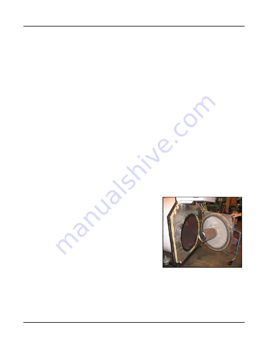
9. The burner door, burner head, blower motor and assembly can now be swung open providing access to the burner
head and combustion chamber.
With the burner head assembly swung open, the burner parts and combustion chamber can be inspected.
A. Check ignition electrodes for deposits and proper gap.
Clean or replace as required. Refer to Figs.
5-6
and
5-7
.
B. Check the burner canister for any damage, burn marks,
or perforations. Replace if damaged. If the canister is in
good condition, clean out any dirt or dust with a vacuum
cleaner or low-pressure air hose.
C. Inspect door refractory and patch any cracks.
D. Inspect the pressure vessel and combustion chamber
area for any damage or residue. If dirt or contaminants
are found, it is recommended that the tube sheet and
tubes be washed with a high-pressure power washer.
E. Replace the burner door gasket. New gasket should be
properly situated in door gasket seat.
Figure 5-3 Burner assembly open
Summary of Contents for ClearFire CFH
Page 14: ...Chapter 1 Introduction 1 8 Part No 750 295 ...
Page 27: ...Chapter 2 Installation Part No 750 295 2 13 Figure 2 10 CFH wiring diagram typical 10 60 HP ...
Page 42: ...Chapter 3 Flue and Combustion Air Venting 3 14 Part No 750 295 ...
Page 90: ......
Page 92: ...Chapter 6 Model CFH Parts 6 2 Part No 750 295 6 1 CONTROL PANEL 10 60 HP ...
Page 93: ...Chapter 6 Model CFH Parts Part No 750 295 6 3 6 1 CONTROL PANEL 70 80 HP ...
Page 100: ...Chapter 6 Model CFH Parts 6 10 Part No 750 295 Standard gas train 30 HP ...
Page 105: ...Chapter 6 Model CFH Parts Part No 750 295 6 15 6 4 2 Gas Train Dual Fuel 30 HP dual fuel ...
Page 106: ...Chapter 6 Model CFH Parts 6 16 Part No 750 295 40 HP dual fuel ...
Page 107: ...Chapter 6 Model CFH Parts Part No 750 295 6 17 50 60 HP dual fuel ...
Page 110: ...Chapter 6 Model CFH Parts 6 20 Part No 750 295 40 HP dual fuel lgp ...
Page 111: ...Chapter 6 Model CFH Parts Part No 750 295 6 21 50 60 HP dual fuel lgp ...
Page 112: ...Chapter 6 Model CFH Parts 6 22 Part No 750 295 6 4 4 Gas Train Propane 30 HP propane ...
Page 113: ...Chapter 6 Model CFH Parts Part No 750 295 6 23 40 HP propane ...
Page 114: ...Chapter 6 Model CFH Parts 6 24 Part No 750 295 50 60 HP propane ...
Page 120: ...e mail info cleaverbrooks com Web Address http www cleaverbrooks com ...