


Chapter 2 — Installation
2-6
Part No. 750-295
2.5.3 Gas Connections
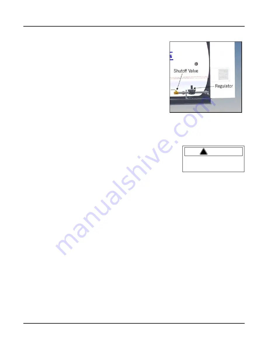
Gas Shut Off Valve and Gas Filter -
A manually operated shut-off valve
and pressure regulator are provided as standard on the CFH boiler (
). In some cases, local regulations may require the installation of an
approved gas filter between the gas shut-off valve and the boiler. Please
ask the local gas supply company whether any such regulations apply.
The boiler should be installed so that the gas ignition system
components are protected from water (dripping, spraying, etc.) during
appliance operation and service.
The CFH boiler may operate without a step-down regulator with gas
pressures <1/2 psig (14" w.c.). A step-down regulator is required above
1/2 psig supply pressure. If a step-down regulator includes a vent
connection, proper gas venting will be required and must be piped to a
safe point of discharge. A dedicated gas pressure regulator is
recommended for each boiler to ensure consistent gas pressure at the
boiler. At supply gas pressures above 2 psig, the use of a true lock-up
type regulator with internal relief is highly recommended.
Drip legs are required on any vertical piping at the gas supply to each
boiler so that any dirt, weld slag, or debris can deposit in the drip leg
rather than into the boiler gas train. The bottom of the drip leg should be removable without disassembling any
gas piping. The connected piping to the boiler should be supported from pipe supports and not supported by the
boiler gas train or the bottom of the drip leg.
All gas piping and components to the boiler gas train connection must comply
with NFPA 54, local codes, and utility requirements as a minimum. Only gas
approved fittings, valves, or pipe should be used. Standard industry practice for
gas piping is normally Schedule 40 black iron pipe and fittings.
Before starting the unit(s) all piping must be cleaned of all debris to prevent its'
entrance into the boiler gas train. Piping should be tested as noted in NFPA 54
and the boiler must be isolated during any tests.
After initial startup, the inlet screen to the gas valve should be checked and cleaned for any debris buildup.
Gas Supply Pipe Sizing -
For proper operation of a single unit or a multiple unit installation, we recommend that
the gas piping be sized to allow no more than 0.3" w.c. pressure drop from the source (gas header or utility
meter) to the final unit location. Higher supply pressure systems may allow for a greater pressure drop. In ALL
cases, minimum supply pressures must be met for proper operation of the boiler(s). The gas supplier (utility)
should be consulted to confirm that sufficient volume and normal pressure are provided to the building at the
discharge side of the gas meter or supply pipe.
For installations of new boilers into an existing building, gas pressure should be measured with a manometer to
ensure sufficient pressure is available. A survey of all connected gas-using devices should be made. If appliances
other than the boiler or boilers are connected to the gas supply line, then a determination must be made of how
much flow volume (cubic feet per hour) will be demanded at one time and the pressure drop requirement when
all appliances are firing.
The total length of gas piping and all fittings must be considered when sizing the gas piping. Total equivalent
length should be calculated from the utility meter or source to the final unit connection. As a minimum guideline,
gas piping
Table 2-2
and
Table 2-3
should be used. The data in these tables is from the NFPA 54 source book,
2006 edition.
To verify the input of each device that is connected to the gas piping, obtain the btu/hr input and divide this
input by the calorific value of the gas that will be utilized. For instance, a 40 HP unit with 1,613,253 btu/hr
input divided by a gas calorific value of 1060 will result in a flow of 1,522 cubic feet per hour. The single boiler
is approximately 20 feet from the gas supply header source. And with a measured gas supply pressure of 10"
w.c. we find from
Table 2-2
that a supply pipe size of 2" should be used as a minimum.
Figure 2-6 Gas shut-off valve and
step-down regulator
!
Warning
A sediment trap must be pro-
vided upstream of the gas
controls.
Summary of Contents for ClearFire CFH
Page 14: ...Chapter 1 Introduction 1 8 Part No 750 295 ...
Page 27: ...Chapter 2 Installation Part No 750 295 2 13 Figure 2 10 CFH wiring diagram typical 10 60 HP ...
Page 42: ...Chapter 3 Flue and Combustion Air Venting 3 14 Part No 750 295 ...
Page 90: ......
Page 92: ...Chapter 6 Model CFH Parts 6 2 Part No 750 295 6 1 CONTROL PANEL 10 60 HP ...
Page 93: ...Chapter 6 Model CFH Parts Part No 750 295 6 3 6 1 CONTROL PANEL 70 80 HP ...
Page 100: ...Chapter 6 Model CFH Parts 6 10 Part No 750 295 Standard gas train 30 HP ...
Page 105: ...Chapter 6 Model CFH Parts Part No 750 295 6 15 6 4 2 Gas Train Dual Fuel 30 HP dual fuel ...
Page 106: ...Chapter 6 Model CFH Parts 6 16 Part No 750 295 40 HP dual fuel ...
Page 107: ...Chapter 6 Model CFH Parts Part No 750 295 6 17 50 60 HP dual fuel ...
Page 110: ...Chapter 6 Model CFH Parts 6 20 Part No 750 295 40 HP dual fuel lgp ...
Page 111: ...Chapter 6 Model CFH Parts Part No 750 295 6 21 50 60 HP dual fuel lgp ...
Page 112: ...Chapter 6 Model CFH Parts 6 22 Part No 750 295 6 4 4 Gas Train Propane 30 HP propane ...
Page 113: ...Chapter 6 Model CFH Parts Part No 750 295 6 23 40 HP propane ...
Page 114: ...Chapter 6 Model CFH Parts 6 24 Part No 750 295 50 60 HP propane ...
Page 120: ...e mail info cleaverbrooks com Web Address http www cleaverbrooks com ...