17
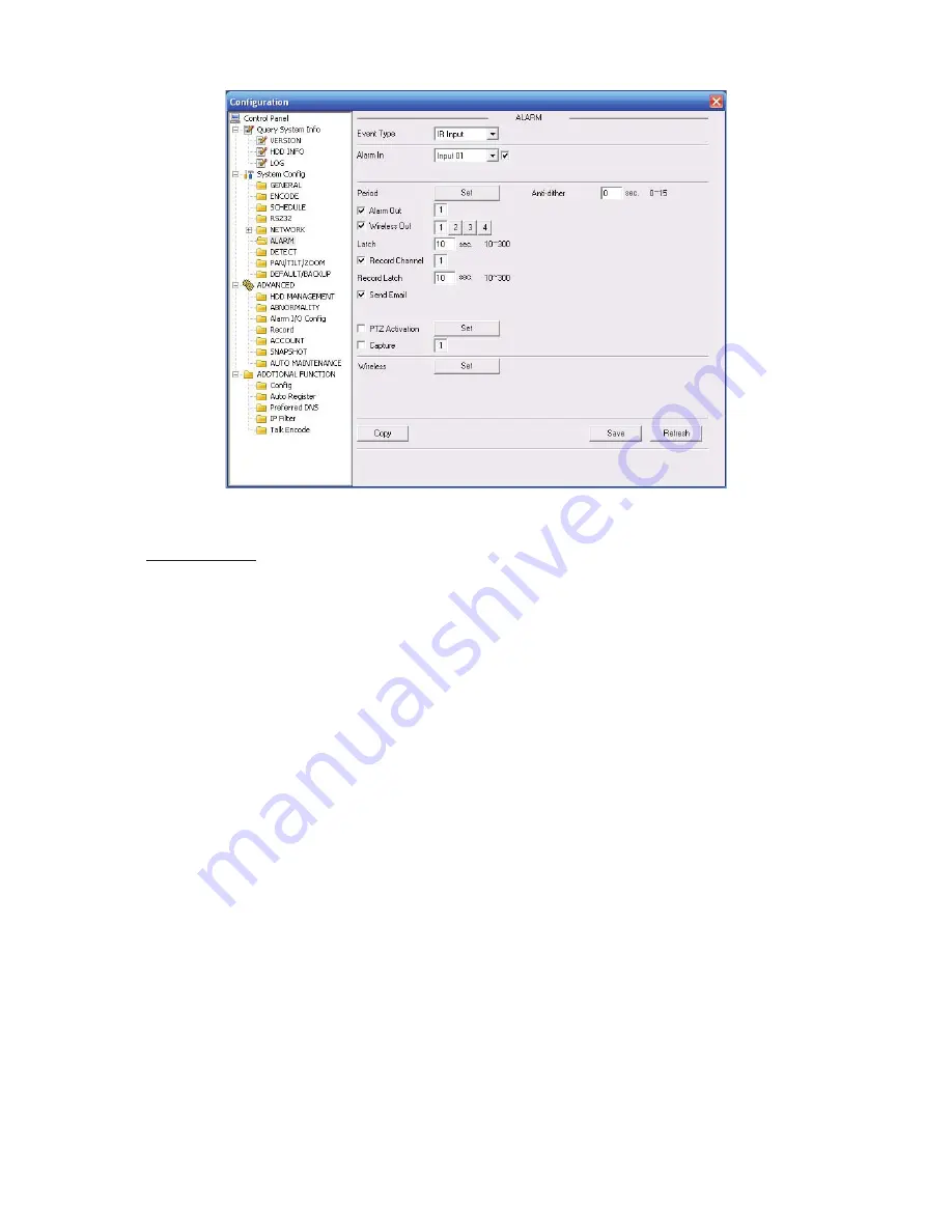
Figure 2-11
Wireless Setup
In Figure 2-11, click wireless Set button, you can see an interface is shown as in See Figure 2-12.
Please follow the steps listed below.
1) Alarm input: Please select the corresponding alarm input port. System max supports 8 alarm
devices. You can input the self-defined name here. After the coding, you can automatically get
the address. The latch time ranges from 0 to 65535.
2) Coding: Please click the coding button of the wireless alarm box, you can see the yellow light
flashes, the device can activate the wireless input device to code. After the coding, the yellow
coding status indication light can prompt the corresponding dialogue box.
3) Clear the address: Please click the coding button of the warless alarm box; you can see the
yellow coding status indication light becomes flash. Then please press the coding button for 5
seconds to clear all the wireless alarm device addresses.
4) Alarm output: Please select the corresponding alarm output port and then input the self-
defined user name. System max supports 4 alarm output devices. Finally you can manually set
the alarm output device address and then save.
5) Remote control: Select remote alarm device and then input self-defined name. Address:
System can automatically get the address after coding. Please refer to the above information to
coding or clear the address.
Summary of Contents for PTZ Series
Page 1: ......
Page 2: ......
Page 3: ......
Page 4: ......
Page 5: ......
Page 6: ......
Page 7: ......
Page 8: ......
Page 9: ......
Page 10: ......
Page 11: ......
Page 12: ......
Page 13: ......
Page 14: ......
Page 15: ......
Page 16: ......
Page 17: ......
Page 18: ......
Page 19: ...Home Use IP Camera PTZ Series Quick Start Guide Version 1 2 ...
Page 30: ...8 Figure 2 4 ...
Page 33: ...11 Figure 3 5 ...
Page 38: ...Home Use IP Camera PTZ Series User s Manual Version 1 2 ...
Page 66: ...23 Figure 3 4 ...
Page 69: ...26 Figure 4 5 ...
Page 76: ...Home Use IP Camera PTZ Series Web Operation Manual Version1 2 ...
Page 98: ...20 Figure 3 11 Schedule Figure 3 12 Storage Set ...
Page 108: ...30 Figure 3 23 General Alarm Setup Figure 3 24 Wireless setup ...
Page 136: ...58 RJ RXW Click log out button system goes back to login interface See Figure 7 1 Figure 7 1 ...
Page 145: ......


